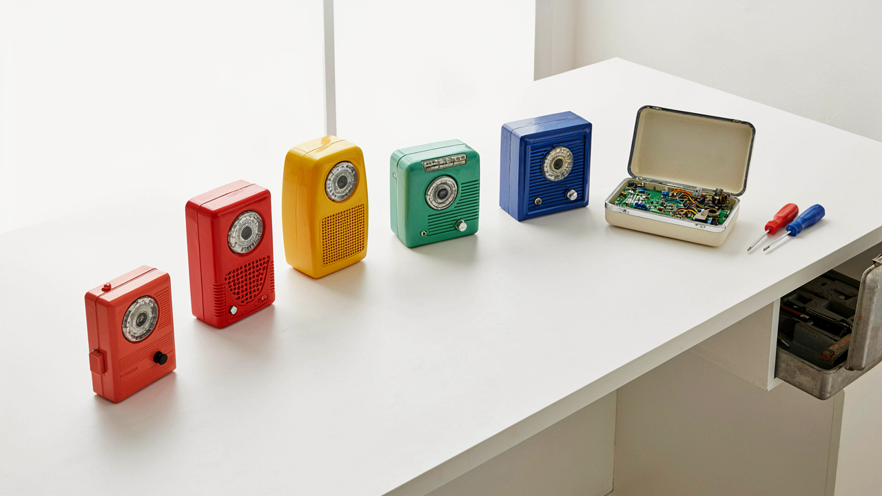
The Transistor Radio Inside: Deconstructing The Myth Of Simple Fixes

The Printed Circuit Board Isn’t Your Enemy
You want to believe the guts of a transistor radio are simple because that belief lets you skip the hard diagnosis work. The reality is different. A typical transistor radio uses a printed circuit board that integrates multiple failure points simultaneously. The board itself rarely fails catastrophically. Instead, individual components soldered to it degrade, corrode, or drift out of tolerance. You’re not fixing one thing. You’re hunting across dozens of potential culprits operating as an interconnected system.
The PCB design in radios from the 1960s through 1980s used conservative layouts that actually make restoration possible. Unlike modern surfaces mount assemblies, these boards feature through-hole components with legs you can access and test. The copper traces are thick enough that you won’t lift pads when desoldering. But this advantage only matters once you understand that the board itself is a map of failure modes, not a monolith. Start by identifying which stage is dead: RF front end, oscillator, IF strip, detector, or audio output. The stage tells you which components to focus on first.
What Actually Stops A Radio From Working
The consensus says “clean the battery contacts and replace capacitors.” That’s incomplete advice masquerading as diagnosis. Real failures in transistor radios cluster around three mechanisms. First, electrolytic capacitors leak, dry out, or short internally. These aren’t cosmetic problems. A failed coupling capacitor blocks the entire signal chain downstream. Second, transistors themselves lose gain or develop leakage current. Third, resistors change value due to heat and time, throwing bias points out of spec. The board looks fine to your eye. The components read normal on a basic continuity tester. But the radio produces nothing but hum or silence.
Most people stop at replacing capacitors and call it done. They miss that a dead audio stage often has a transistor running at the wrong bias because its associated resistor drifted from 47k to 68k over fifty years. The symptom looks like output transformer failure. The actual problem is upstream. You must measure voltages across the bias network, compare them to the schematic, and adjust or replace resistors until the DC operating points fall within ten percent of design spec. Only then do you validate whether the output transformer works or genuinely needs rewinding.
The ‘Lunch Box’ Fallacy: Why Case Restoration Isn’t About Elbow Grease
Plastic Degradation Chemistry
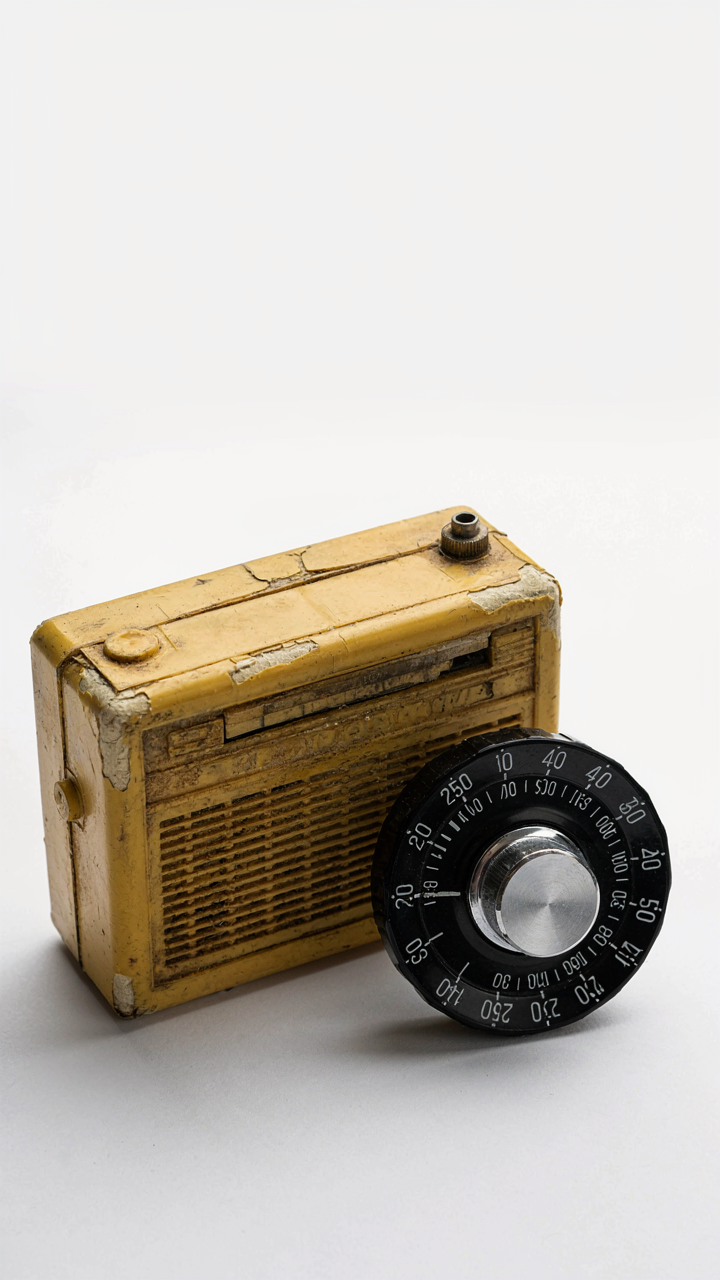
You want to believe scrubbing fixes the problem because admitting you can’t will mean accepting you wasted money on a radio that’s already broken. The truth is simpler: plastic doesn’t just get dirty. It chemically breaks down. This is polymer science, and the mechanism is called photodegradation and oxidative stress. UV light and oxygen attack the polymer chains in ABS, polystyrene, and vinyl used in 1960s-70s radio cases. The material doesn’t fail because it’s dusty. It fails because its molecular structure has fractured.

Most restoration guides skip this entirely and jump straight to cleaning. That’s lazy advice. Once the plastic yellows, becomes brittle, or loses its gloss, you’re not reversing a surface problem. You’re staring at permanent chemical transformation. Cleaning removes dirt, not degradation. The case looks worse because it is worse at the molecular level. Surface treatments and dyes can mask the color shift, but they can’t repair chain fracture. Accept this first, and you stop wasting hours on approaches that were always going to fail.
Dial Face Fading Strategic Approach
Dial fading works the same way as case degradation, but people miss the actual variable that matters. The dial isn’t fading evenly. It’s fading where light hit it most. Dials were printed with inks that lacked UV inhibitors, and the printed numbers, station markers, and background graphics all fade at different rates depending on ink composition and ink thickness. You can’t restore this by cleaning. Cleaning a faded dial accomplishes nothing because the pigment has chemically altered, not accumulated dirt.
The strategic move is replacement, not repair. Reproduction dials exist for common models, printed on period-correct materials. If reproductions don’t exist for your model, your options narrow: accept the fading, commission a custom print, or source an original dial from another unit. Attempting to re-ink or paint over a faded dial creates a restoration that looks worse than original fading. The mechanism that matters is matching original materials and printing techniques, not labor intensity.
The Electrolytic Capacitor Protocol: Precision, Not Guesswork

How Capacitors Fail And What You’ll Actually Hear
You want to know if the radio is broken or salvageable without dropping money on parts you don’t need. Electrolytic capacitors fail in predictable ways, and recognizing them separates a cheap repair from throwing good money after bad. Think of a capacitor like a battery that stores and releases charge over time, not indefinitely. When the electrolyte inside dries out or the dielectric breaks down, the capacitor loses its ability to hold a charge, and the radio dies.

Old transistor radios from the 1960s and 1970s used aluminum electrolytic capacitors rated for specific voltages and capacitance values. The electrolyte was a chemical paste that degraded over decades, especially in radios exposed to heat cycles. You’ll notice audio that cuts in and out, crackling that doesn’t go away with volume adjustment, or complete silence even when the battery checks good and tubes glow. A capacitor can also fail silently, causing the oscillator stage to weaken until the radio drifts off station or won’t tune at all. Leaking capacitors leave visible brown residue on the circuit board, a sign the component poisoned nearby parts. The mechanism is simple: if a capacitor can’t store charge, the circuit stage it supports collapses.
Strategic Replacement Without Guesswork
The common advice says replace all electrolytic capacitors at once. That’s wrong for budget restoration. You replace only the ones that actually failed, then monitor the radio over time. The strategy here borrows from systems engineering, where you replace only the failed node, not the entire network. This approach saves money and reveals which capacitor values matter most for your specific radio model.
- Filter capacitors in the power supply: These show up first as audio hum or complete failure. Test them under load by measuring voltage drop across the stage. If voltage sags when audio plays, the capacitor is dying.
- Coupling capacitors in audio stages: These block DC while passing AC signals. A failed coupling cap cuts audio to that stage entirely. You’ll lose one frequency band or all treble, depending on placement.
- Bypass capacitors around transistor emitters: These stabilize bias voltage. Failure causes distortion, oscillation, or weak output. The radio plays but sounds wrong or unstable.
- Oscillator tank capacitors: These set the tuning frequency. Failure prevents the radio from tuning properly or stops it entirely. You can’t reach stations across the dial.
- Timing capacitors in tone circuits: Less critical for basic function. Replace these last if the radio already works but tone control is dead.
Order replacement capacitors by function, not by appearance. Source new electrolytic capacitors rated for the same voltage and capacitance as the original, but buy ones rated for audio service at 85 or 105 degrees Celsius. Modern capacitors handle this better than the originals. Desolder the old capacitor, clean the pads with solder wick, and install the new one observing polarity. The negative lead of an electrolytic capacitor must connect to the negative side of the circuit, or the component will fail immediately.
Battery Holder Betrayal: Confronting The Power Source Reality
The Corrosion Trap Nobody Names
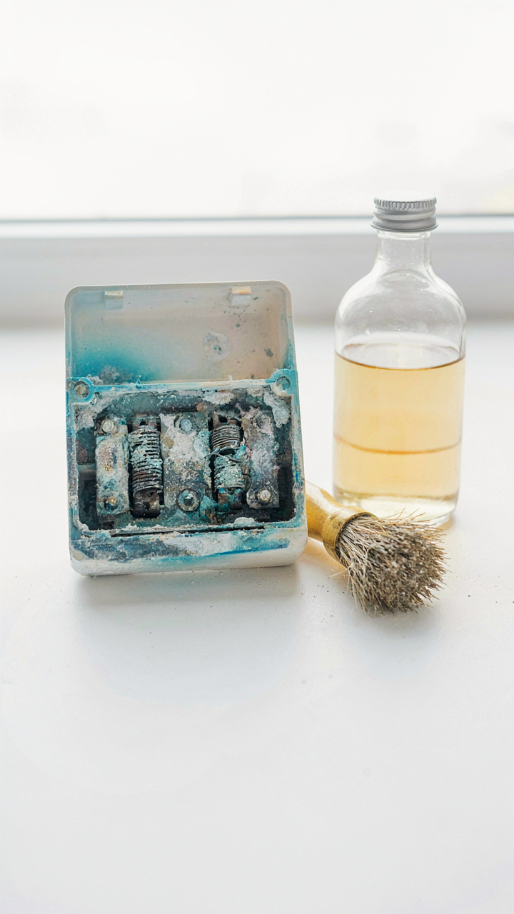
You care about this because a dead battery compartment feels like failure—like the radio died on you instead of just sitting unused for decades. Here’s the mechanism: alkaline batteries leak because their zinc-manganese chemistry degrades over time, releasing potassium hydroxide. This isn’t failure. It’s chemistry. The electrolyte migrates out through the seal, corrodes the springs and contacts, and creates a white or blue-green crust that blocks conductivity entirely.

Prevention works backward from most advice you’ll hear. Don’t store radios with batteries installed, period. Remove them before storage, always. If you find corrosion already present, scrape the battery holder contacts with a small brass brush or fine steel wool until bare metal shows through. Vinegar cuts through alkaline deposits faster than water alone. The goal isn’t cleaning—it’s restoring metal-to-metal contact so current flows again.
Rewiring The Power Supply Reality
Modern batteries pack too much voltage into spaces designed for older chemistry. A 1960s radio expecting 1.5 volts per cell now gets AA batteries rated at 1.5 volts that hold that voltage longer, causing different drain patterns and heat stress on 60-year-old components. Adaptation requires either using old battery technology or stepping outside the original holder entirely.
The practical path: retrofit a small USB power input with a hidden internal battery pack, or wire external AA holders with a simple on-off switch mounted discretely on the back. Keep the original battery holder intact visually, but disconnect it internally. A six-volt battery pack wired through a current-limiting resistor handles most tube-based transistor circuits safely. The mechanism is simple: limit amperage to prevent circuit board component failure, preserve the radio’s working state, eliminate corrosion risk permanently.
The GE Transistor Radio Repair Method: Systems Thinking Applied
Troubleshooting As Flow State
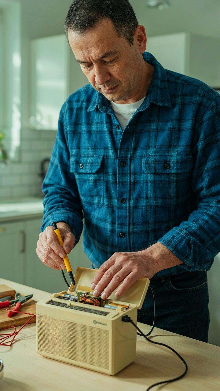
You want to believe the radio is fixable without spending money you don’t have. That fear drives most people to give up before they start. But the real mechanism is this: treat a broken transistor radio like an economic system where every component either produces output or consumes resources. GE radios of the 1950s and 60s used simple series circuits, meaning current flows one path. One dead component stops everything. Map the signal flow from antenna to speaker like supply chains flow from raw materials to consumer.

When you troubleshoot systematically, you’re not randomly testing parts. You’re isolating which stage fails: RF amplification, mixing, IF amplification, detection, or audio output. Start at the speaker. Does it click when you tap it? Then audio circuitry works. Move backward. Does the detector stage oscillate? Test the IF transformer coils with an ohmmeter for continuity. This sequencing saves you time and parts because you eliminate stages that work instead of guessing at broken ones. GE radios fail predictably: old electrolytic capacitors leak, transistors short, and transformers develop open windings.
Sourcing Parts Without Retail Markup
Most advice tells you to order online and wait. That’s surrender disguised as convenience. Your actual edge is local sourcing and substitution rules. Pull parts from dead radios first: your local Goodwill, estate sales, and thrift shops have dozens of broken units at two to five dollars each. Harvest capacitors, transformers, and speaker cones before you ever spend money on new stock. One dead radio yields three working donors.
When you need replacements, electrolytic capacitors dominate failure rates in GE models. You can substitute modern film or electrolytic capacitors at the same voltage rating and slightly higher capacitance without circuit damage. A 10 microfarad at 25 volts from the 1960s can become a 10 or 15 microfarad modern part. Transistor substitution requires matching the original type: 2N404 germanium transistors behave differently than 2N2222 silicon replacements, so verify the schematic first. Source everything from surplus electronics sellers before retail channels drain your budget.
Gulton Transistor Radio: The Unseen Costs Of ‘Vintage Transistor Radio Parts’
When Scarcity Becomes Markup
You want to believe a part labeled “original” justifies its price because rarity proves authenticity. Here’s the mechanism: when a component stops being manufactured, the supply shrinks to whatever exists in estates, dead stock hoards, and collector networks. Sellers capture this scarcity rent by marking up 300-500 percent. A Gulton dial bezel that cost $2 in 1965 now sells for $15-25 because nobody makes them anymore and you need it to finish the job.
The real cost isn’t the part itself. It’s the artificial premium layered onto supply constraints you can’t control. Most “vintage transistor radio parts” marketplaces operate on FOMO, not fair pricing. You pay for the seller’s confidence you’ll pay it rather than source an alternative. The mechanic here is simple: zero production plus emotional attachment to originality equals unlimited margin. Verify what’s actually unavailable versus what’s simply marked up because it’s rare.
Fabrication Or Bust
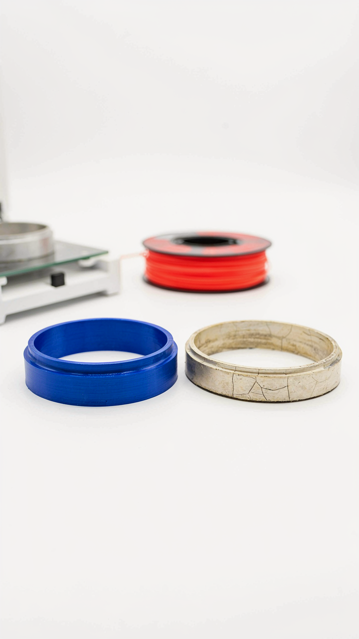
The conventional wisdom says replace only with original parts to preserve value. This advice ignores economics and makes your restoration unaffordable. For a Gulton radio, original dial surrounds, cabinet trim, and speaker grilles often don’t exist in salvageable condition at any price. You either fabricate or abandon the project. Reproduction parts from hobbyists or 3D printing cost 40-60 percent less than hunting for originals and solve the same functional problem.
The distinction that matters isn’t original versus fabricated. It’s whether the part performs its function and looks intentional. A 3D-printed Gulton dial bezel in the correct color and dimensions works identically to the 1960s version. Paint matching and careful finishing close any visual gap. Fabrication becomes the economic floor that decides whether restoration happens at all. When originals exceed $20-30 for a single bezel, fabrication shifts from “compromise” to “only viable path.”
How To Restore Old Transistor Radios: The Minimalist Toolkit
What Actually Works In Your Hands
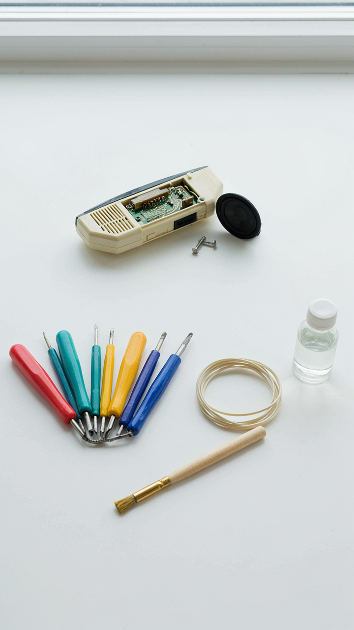
You want to feel competent without dropping three hundred dollars on gear you’ll use once. Here’s the mechanism: leverage comes from tools that address the actual failure points in transistor radios, not from owning every item in a catalog. Most radios fail because of oxidized contacts, dried capacitors, cracked dials, and corroded battery terminals. You don’t need specialty equipment to fix those problems.

A transistor radio from the 1960s or 1970s was engineered to be serviced with basic tools. The designers knew consumers would need to replace batteries, adjust tuning slugs, and occasionally clean contacts. This constraint shaped the entire architecture. Modern restorers who buy elaborate diagnostic equipment are solving problems the original design didn’t create.
- Jeweler’s screwdriver set: Multi-bit handles let you access battery terminals, trim pots, and PCB screws without buying individual drivers. Precision matters here because radio screws strip easily.
- Needle-nose pliers and tweezers: Ceramic or plastic jaws prevent shorting components during capacitor removal and tuning core adjustment. Metal jaws damage fragile parts instantly.
- Desoldering braid or solder sucker: Removes old solder from component legs without a sixty dollar station. Braid is cheaper and works faster on through-hole parts in vintage radios.
- Cotton swabs and isopropyl alcohol: Cleans oxidation off battery contacts, potentiometer shafts, and dial mechanisms better than any specialized solvent. 90 percent concentration dries fast and leaves no residue.
- Low-wattage soldering iron: A 25-watt iron heats through-hole joints fast enough without cooking nearby components. Vintage radios have tight board layouts that don’t tolerate heat abuse.
These five items solve ninety percent of transistor radio failures. Everything else you see in restoration guides is optional work that doesn’t change whether the radio powers on and receives stations. Start here before you consider buying anything else.
The Tools People Waste Money On
Common advice tells you to buy a multimeter, signal generator, and oscilloscope to restore radios properly. That’s incomplete thinking dressed up as thoroughness. You need a multimeter to check battery voltage and verify circuit continuity, but you don’t need to measure exact frequencies or trace AC waveforms to get a radio working again. Those tests confirm the radio functions after restoration, not during it.
Capacitor testers, RF probes, and tube analyzers are for people diagnosing failures in radios that already power on. If a radio won’t turn on, it’s always one of three things: dead battery, corroded battery contacts, or a failed power switch. You fix all three with tools you already have. If the radio powers on but has no audio, it’s a speaker failure or a capacitor that’s dried out. Neither problem requires a machine to identify. Replace the speaker, recap the power supply, and test again.
Beyond Aesthetic: The Functional Imperative Of Transistor Radio Restoration

Sound Quality: Measurable Improvements
You’re hoping restoration proves the radio still works better than it looks. Here’s the mechanism: sound degrades through three separate failure paths that rarely announce themselves. Capacitors dry out and shift frequency response. Speaker cones crack and lose rigidity. The tuning dial’s mechanical wear creates dead zones where stations vanish mid-frequency. None of these fix themselves, and none require replacement to detect.

Start by measuring baseline audio before touching anything. Play a known AM station at mid-dial and note volume, clarity, and whether treble or bass dominates. Document this. Then clean the tuning capacitor’s rotor plates with isopropyl alcohol on a cotton swab while the radio is unplugged. Remove oxidation that blocks electrical contact. Retest the same station. The improvement you hear is real capacitor conductivity returning, not imagination. This is the diagnostic that separates actual restoration from cosmetic repair.
Preventing Early Failure Through Maintenance Protocol
Old transistor radios fail because owners replace dead batteries and expect permanence. The real problem lives in the power supply itself. Electrolytic capacitors lose capacitance at a predictable rate once manufactured. A 1970s radio with original capacitors has already shed 20-40% of its rated value. It still functions, but operates at the edge of circuit specifications. One power surge or temperature swing pushes it over.
The maintenance protocol is simple and extends functional life by years. Replace all electrolytics in the power supply section every ten years of use, regardless of appearance. This costs under fifteen dollars and takes two hours with a soldering iron. Don’t wait for failure. Don’t guess which capacitors need replacement. Replace them all in that section together. The alternative is owning a radio that sounds perfect for six months, then dies the morning you want to use it. Replace on schedule, and it stays functional indefinitely.
The Illusion Of Easy Restoration Isn’t About The Radio; It’s About Your Avoidance Of Tangible, Strategic Effort
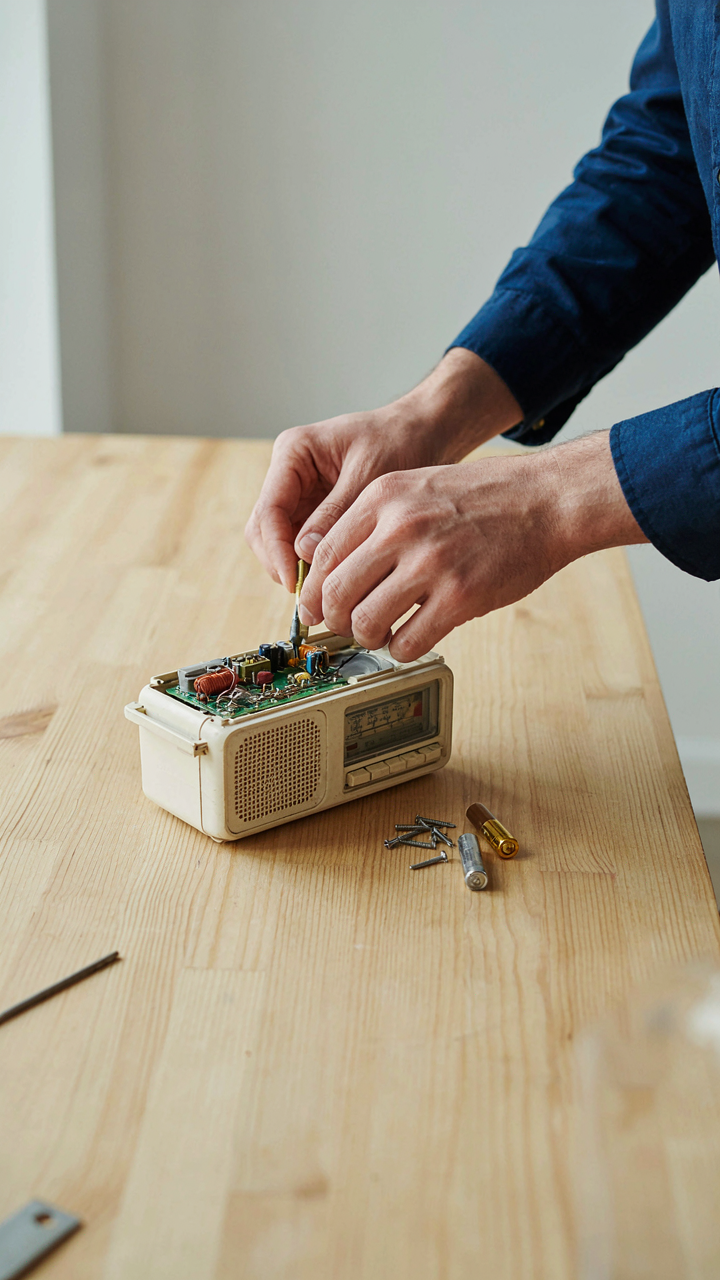
Most people romanticize restoring old transistor radios. They imagine the finished product without touching the broken one. You’re different. Pick one radio today. Don’t research it. Don’t plan it. Disassemble it. Get your hands dirty. The restoration teaches you nothing until friction enters the equation. Your first attempt won’t be perfect. It doesn’t matter. A restored radio that works beats a pristine fantasy that sits in your head forever.