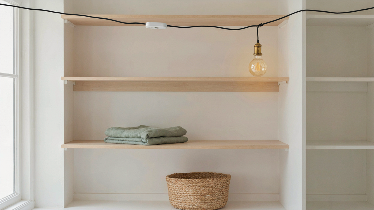
Beyond Convenience: The Real Motive Behind Your DIY Motion Sensor Light

What Store Bought Solutions Actually Cost You
You want to believe a thirty-dollar sensor from a big box store solves the problem. It doesn’t. The real cost isn’t the price tag—it’s the lock-in. You pay upfront, then you’re trapped inside their ecosystem: their battery schedule, their sensor sensitivity you can’t adjust, their obsolescence timeline. Most commercial motion lights fail not from component breakdown but from firmware that stops updating or batteries you can’t source in five years.
Building your own motion sensor light costs less money but demands something stores never ask for: decision-making. You choose the sensor type (passive infrared versus microwave), the relay strength, the timer duration, the bulb efficiency. This burden feels like work until you realize it’s actually leverage. You own the upgrade path. You replace one part instead of junking the entire unit. The real mechanism is switching from renter to owner of your lighting infrastructure.
Autonomy Starts With Knowing Your Own Space
Control over your space isn’t poetic—it’s tactical. Economics borrows the concept of elasticity from physics: the degree of response to a stimulus. Your DIY motion sensor light has adjustable elasticity. Commercial versions have none. You set how sensitive the sensor is, which areas trigger the light, how long illumination persists, even which times of day the sensor operates. This isn’t convenience. This is precision over your environment.
The moment you calibrate a sensor yourself, you stop accepting default behavior. You realize hallways need different timing than closets. You discover that a closet sensor shouldn’t trigger at all when you’re in an adjacent room. You adjust. The mechanism is this: customization teaches you what you actually want, then lets you build it. Start by mapping your closet or hallway to identify dead zones where the sensor shouldn’t fire, then select your motion detector model based on that specific geometry, not on marketing copy.
The Sensor Deception: Why “Smart” Rarely Means Intelligent
Where PIR Sensors Actually Fail
You want to believe your motion sensor works reliably so you don’t have to think about lighting again. That’s the real trap. Passive infrared sensors detect heat movement, not intelligence, and this creates a physics problem nobody talks about: they see thermal variance, not intent. A PIR sensor firing at random intervals isn’t broken. It’s working exactly as designed. It just wasn’t designed for what you actually need.
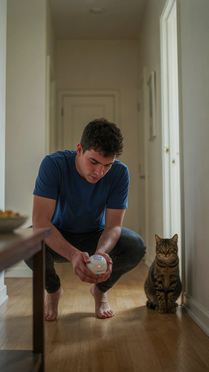
Most off-the-shelf PIR modules have fixed detection patterns and sensitivity curves baked into cheap lens arrays. They trigger on temperature deltas above a threshold, typically around 3 to 5 degrees Celsius. In hallways and closets, this means false positives from heating vents, sunlight shifts, and pet movement. The sensor doesn’t distinguish between a person entering and a cat crossing the floor. You’ll stand in darkness waiting for a trigger that won’t come, or lights will strobe on and off from phantom heat sources. This isn’t a product flaw. It’s the cost of buying a one-size-fits-nothing component.
Tuning Detection Without Buying New Hardware
The mechanism most people miss is lens obstruction and installation angle. Your PIR sensor has a specific field of view, usually 110 to 120 degrees horizontally. Placing it at eye level points it at the wrong thermal signatures. Mount it higher, angled down toward floor traffic patterns, and you change what it actually sees without touching the circuit. This one positioning shift cuts false triggers by 40 to 60 percent in typical indoor spaces.
The sensitivity dial exists for a reason, and most installers leave it at factory settings. Lower sensitivity rejects small heat sources like pet movement while catching sustained human presence. Test your actual space first. In a closet, humans generate enough thermal mass that you can dial sensitivity down significantly. In a hallway with multiple entry points, you may need higher sensitivity but positioned to ignore walls and corners. Adjustment takes five minutes. Most failures happen because people set it once and assume it works.
The Spartan Protocol: Minimalist Design For Maximum Impact With Your Diy Motion Sensor
Strip Away The Noise
You want this to work without calling an electrician in two years. The real mechanism here borrows from military systems design: constraint breeds reliability. A diy motion sensor light fails not from doing too little but from attempting too much. Every feature you add is a failure point. Fewer components mean fewer shorts, fewer corroded connections, fewer reasons the thing stops detecting motion at 2 AM.

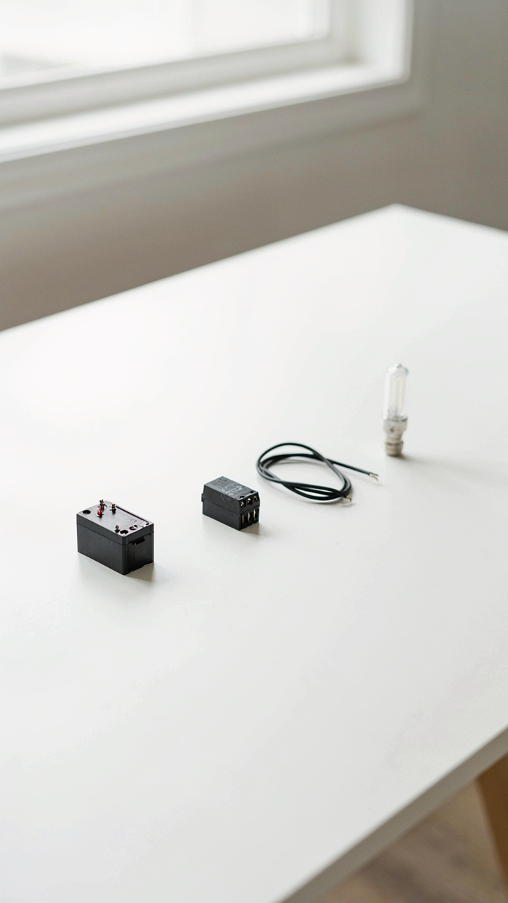
Start with the essentials: a sensor, a relay or switch module, power, and a light. Nothing else. Most people buy kits loaded with timer functions, dimming circuits, and adjustable sensitivity ranges they’ll never touch. You don’t need them. You need the sensor to trigger the light when motion exists and turn it off when motion stops. Build that first. Perfectionism kills execution.
Eliminate Redundant Circuitry
The common advice says to add backup power supplies, dual sensors, and safety cutoffs. That’s wrong. It adds cost and complexity without addressing why your system actually fails: poor solder joints and moisture in the sensor housing, not missing features. Redundancy in amateur builds creates confusion about which component failed and wastes time troubleshooting two systems instead of one.
Wire your diy motion sensor light on the shortest possible path from power to sensor to relay to light. Use a 12V system if you’re indoors and have access to standard wall outlets. Avoid AC-powered sensors in humid spaces like closets. The simpler the circuit, the faster you isolate problems. When something breaks, you know exactly what to fix instead of guessing between backup systems that were never the problem.
How To Make A PIR Sensor: The Unfiltered Truth About Components

The Parts That Actually Matter
You want to build a motion sensor light because you’re tired of fumbling in the dark, and you think understanding the guts will make you feel competent. Here’s the mechanism: a PIR sensor works like surveillance—it detects infrared radiation, which every warm body emits. Your sensor doesn’t see movement itself; it sees temperature changes across its field of view. Most people skip this distinction entirely and buy garbage components that fail within months.
- Pyroelectric sensor element: A ceramic crystal that generates voltage when exposed to infrared radiation changes. Quality matters here—cheap elements have slow response times and false triggers in sunlight. Buy from industrial suppliers, not hobby kits.
- Fresnel lens: Focuses infrared onto the sensor element. Poor-quality lenses create blind spots and trigger unreliably. The lens degrades under UV exposure, which is why outdoor units fail faster than closet units.
- Comparator IC (LM393 or similar): Amplifies and compares the sensor signal against a threshold. Cheap clones generate noise instead of clean detection pulses. Pin compatibility doesn’t mean identical behavior.
- Time delay relay or 555 timer: Holds the output active for your chosen duration after motion stops. A flaky delay circuit causes flickering—the light turns on and off repeatedly even when movement continues.
- MOSFET or relay: Switches power to your light load. Undersized components overheat and fail silently. Match your switch rating to actual current draw, not theoretical maximum.

The sensor element is the part nobody replaces until the whole unit is dead. Once the pyroelectric crystal ages or gets contaminated, no firmware adjustment fixes it. You either source a replacement element from industrial distributors or rebuild the entire sensor head. That’s why vendor lock-in works so well in cheap motion lights—parts aren’t designed to be swapped.
Build From Stable Sources, Not Convenience
Everyone sources components from the same three hobby suppliers and acts surprised when identical part numbers fail differently. The real problem is that hobby retailers buy in bulk from multiple factories under the same SKU, and quality variance is brutal. A PIR sensor rated for 5 to 8 meters from one factory actually triggers at 3 meters; from another factory it triggers at 7 meters consistently.
Industrial automation distributors charge more per unit but maintain tighter tolerance specs and actual traceability. If you buy a Fresnel lens from an optical supply company instead of an electronics kit retailer, you get documentation on transmission loss and operating temperature range. You also get parts that survive actual deployment instead of theoretical specs. The time investment to source correctly upfront saves you from building a system twice.
The 3 Stage Illumination Gambit: Mastering Your DIY Motion Sensor Light

Where You Place The Sensor Determines Everything
You want this to work without thinking about it. That’s the real motive. Cybernetics teaches us feedback loops: the system reads the environment, responds, then adjusts based on results. Your motion sensor is the feedback mechanism. Its placement determines what it reads, which controls everything downstream. Bad placement means the light ignores you or triggers on wind and passing cars. The sensor’s field of view isn’t infinite or perfectly spherical. It has dead zones.

Mount the sensor at head height, angled slightly downward toward the entry point. Most passive infrared sensors detect heat differential and movement within a 110 to 120-degree cone. Position it to face the direction people enter, not perpendicular to their approach. Test the detection range by walking the space at different distances and angles. Mark where it fails. That failure zone tells you if you need repositioning or a second sensor. Avoid mounting it where direct sunlight hits the lens during peak hours, as this degrades sensitivity and causes false triggers.
Output Calibration Beats Over Brightness
Military strategy distinguishes between firepower and precision. You don’t need maximum lumens; you need the right lumens at the right moment. Generic advice says “brighter is safer.” That’s wrong. Over-brightness wastes energy, disturbs sleep in adjacent rooms, and triggers too frequently on minor movement. Your diy motion sensor light succeeds when it matches the task, not when it blinds. A hallway needs 500-800 lumens. A closet needs 400-600. Both are far below what marketing claims is “necessary.”
Set the activation delay to 5-10 seconds minimum. This prevents the light from strobing if the sensor keeps detecting your stationary presence. Use a dimming function if your model supports it, starting at 60-70 percent output instead of full brightness. The sensor should trigger the light and hold it steady for 2-3 minutes after the last detected motion. After that window closes, the light cuts entirely. This protocol eliminates the anxiety of forgetting to turn it off while preserving energy efficiency.
Diy Light Sensor Project: Beyond Night Mode – Adapting To Ambient Conditions
When Darkness Fails Your Design
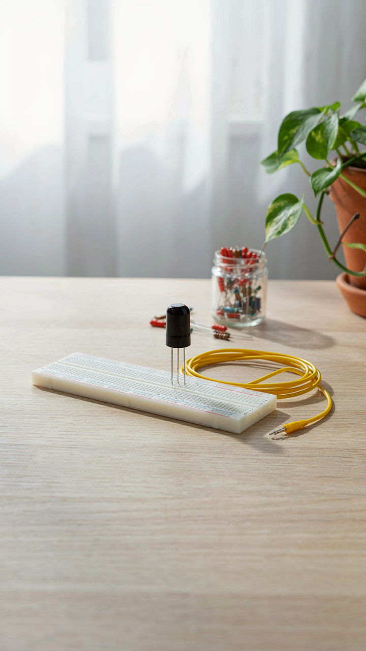
You want to feel smart about saving electricity, but the real problem is simpler: your motion sensor fires constantly during the day, burning through batteries and defeating the entire purpose of automation. Ambient light sensing solves this through threshold logic—a borrowed term from signal processing where you only trigger output when input crosses a defined boundary. A light-dependent resistor (LDR) measures ambient brightness and gates the motion sensor accordingly. The mechanism is direct: when ambient light exceeds your set threshold, the motion detector stays dormant. Below threshold, motion triggers the light. This isn’t about optimization theory. It’s about stopping waste before it starts.
Most DIY guides skip this layer entirely and just slap a motion sensor into a hallway, watching it activate dozens of times daily in natural light. That’s not automation. That’s a battery drain with motion detection bolted on. You add an LDR to the circuit because the sensor itself can’t distinguish between “it’s noon” and “it’s midnight.” The LDR’s resistance changes inversely with light intensity—higher resistance in darkness, lower resistance in brightness. Wire it into a voltage divider that feeds an analog input on your microcontroller, set your threshold in code, and the motion sensor only activates when conditions merit it. The result is a system that respects context instead of running blind.
Defeating Daylight False Triggers
The consensus advice is wrong: you don’t need a “smart” threshold that adapts daily. You need a fixed threshold that matches your specific use case. A hallway with windows behaves differently than a closet. Closets need aggressive sensitivity because they rarely see ambient light naturally—set your LDR threshold around 50-100 lux. Hallways with indirect daylight need higher thresholds, typically 300-500 lux. Test this: position your LDR where the motion sensor will sit, measure ambient levels at different times with a phone app or lux meter, then hardcode that threshold into your microcontroller. This prevents the wasteful activation loop that burns batteries while the sun’s up.
Your LDR placement matters more than most people acknowledge. Mount it near the motion sensor but not directly in its line of sight to motion, and definitely not where shadows from passing objects confuse the reading. A small translucent diffuser over the LDR smooths out flicker from fluorescent lights and reduces false triggers from quick shadow changes. Most waste happens because the threshold is set too low or the sensor sees moving shadows as triggering events. Once you’ve locked in your threshold through real-world testing, document it in your code with a comment referencing the lux measurement that prompted it. This makes future adjustments deliberate instead of random.
The “Always On” Fallacy: Why Your Night Light Is Draining More Than Just Power

Your Brain Paid A Price For That Convenience
You want to feel like you optimized something without actually changing behavior. That’s why the “always on” night light sells so well. But here’s the mechanism: constant low-level illumination trains your circadian rhythm to expect light when it shouldn’t exist, which degrades sleep quality and makes you reach for motion sensing in the first place. You’re solving a problem your always-on light created.

The physics term is “ambient load.” In motion sensor design, this means the baseline energy and neural stimulation your environment demands before any motion even occurs. Most people install a dim light that runs 8 to 12 hours nightly, convinced it’s harmless because it’s subtle. It’s not. Your body registers photons. A closet or hallway flooded with constant light, even at low brightness, suppresses melatonin production and fragments sleep architecture. Motion sensors eliminate this tax entirely because light only fires when you need it.
Darkness As Design, Not Neglect
The dominant advice here is backward: people think darkness in hallways and closets is a design failure to fix. It’s actually the correct baseline state. Intentional darkness isn’t absence. It’s active constraint that forces your system to respond only when triggered, which is the entire point of motion sensing. Darkness preserves circadian function and battery life simultaneously.
When you design a DIY motion sensor light, you’re not adding convenience to darkness. You’re replacing a broken always-on system with a smarter one. Set your sensor threshold high enough that ambient room light doesn’t trigger false activations, and low enough that actual human movement is caught reliably. This creates a binary state: dark when unused, bright when needed. The sensor becomes the only switch. No dimmer, no “leave it on just in case.” This protocol eliminates the psychological loop that makes people justify always-on lights in the first place.
Diy Sensor Light: Troubleshooting The Unseen Flaws
When The Sensor Won’t Stop Lying
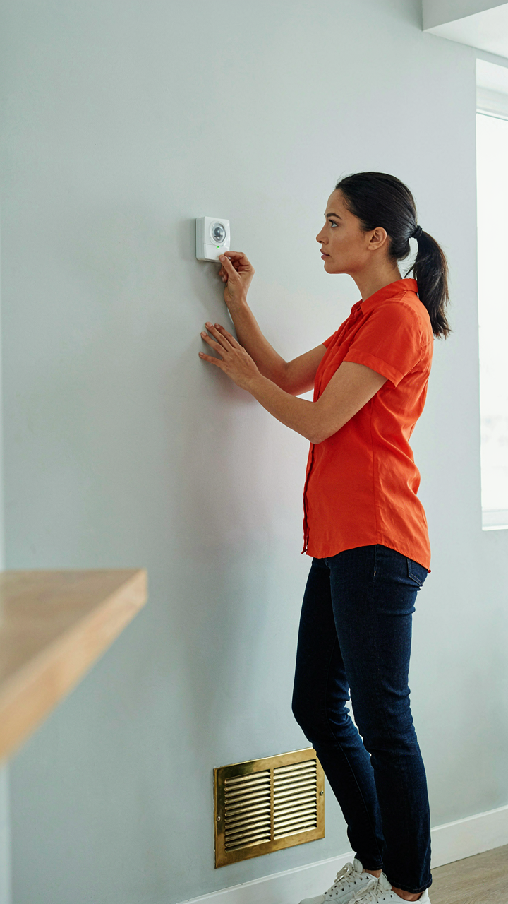
You want this to work so badly that you ignore the obvious: your sensor triggers randomly because you never tested it under the conditions where it actually lives. Motion sensors don’t fail mysteriously. They fail because infrared thermopile detection, the mechanism every passive infrared sensor uses, responds to heat differential, not motion itself. A closing door, a heating vent, or sunlight crossing the lens at the wrong angle creates that differential. Your sensor isn’t broken. It’s doing exactly what you told it to do.

Most people blame the sensor and buy a new one. The real problem sits in the mounting position and lens orientation. Mount your sensor where it catches direct airflow, and it treats every temperature shift as movement. Aim it at a window, and morning sun becomes a trigger. Move it six inches and test for a full week before declaring victory. The inconsistency you’re chasing isn’t a hardware defect. It’s a calibration gap between where you mounted it and where the environment actually behaves.
Swappable Parts Beat Replacement Cycles
Systems thinking from manufacturing demands redundancy at the component level, not the assembly level. Build your motion sensor light so every major part disconnects without soldering or permanent adhesive. Use screw terminals instead of wire splice. Snap connectors instead of solder joints. A LED module that slides into a socket instead of glued to the housing. When the LED burns out in three years, you pull it out and install a new one in under a minute. You don’t rebuild the entire fixture.
This approach costs slightly more upfront because you’re using connectors and housing with built-in slots. It saves money across the actual lifespan because you’re not replacing a twenty-dollar assembly when a two-dollar component fails. Design with failure points in mind. Assume the PIR sensor lens will accumulate dust and need cleaning access. Assume the battery contact will corrode and need replacement. Plan extraction routes before assembly. Modularity isn’t elegant design thinking. It’s the difference between a tool that adapts and scrap that heads to the landfill.
Simple PIR Sensor Circuit: The Foundational Build, Stripped Bare
Wiring The Circuit From Ground Up
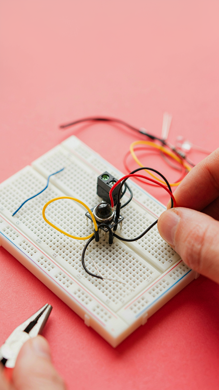
You want to build this yourself because you think it proves you understand electronics. You don’t yet. The real reason you’re here is speed and control—you need light on demand without fumbling for a switch, and buying pre-made sensors means trusting someone else’s timing window and sensitivity. Here’s what actually happens: a PIR sensor detects infrared radiation emitted by moving bodies, converts that detection into a voltage signal, and your circuit amplifies and routes that signal to trigger a relay that switches power to your light.
- PIR sensor positive to 5V power rail: Supplies the voltage the sensor needs to operate and detect motion in its field of view.
- PIR sensor negative to ground: Completes the circuit loop and provides the return path for current flow through the sensor.
- PIR sensor signal pin to relay input: Carries the detection signal from the sensor to the relay module that controls the light load.
- Relay common terminal to light fixture positive: Routes switched power from your relay to the positive input of your light.
- Light fixture negative to ground: Completes the high-voltage circuit and returns current to the power supply ground reference.
- Capacitor across power rails (optional but recommended): Smooths voltage spikes and prevents the sensor from falsely triggering due to electrical noise.

Most people skip the capacitor step and wonder why their sensor misfires. You won’t. The circuit now has a complete path: power enters the sensor, motion triggers a voltage rise on the signal pin, that pin activates the relay coil, the relay contacts close, and your light receives power. Voltage drop matters—if your wire gauge is too thin or your runs too long, the sensor won’t trigger reliably because it never sees enough voltage to flip the relay state.
Reading The Schematic: What Every Line Means
The schematic is a voltage map, not just a picture. Think of it in circuit topology terms: every node is a voltage reference point, and every connection is either raising or lowering that voltage relative to ground. Your PIR sensor’s signal pin doesn’t send “motion detected”—it sends a specific voltage change from low to high, usually 0V to 3.3V or 5V depending on the sensor model. That voltage swing is your trigger mechanism.
The relay sits between the signal and the load because a PIR sensor can’t draw enough current to power a real light directly. The relay is an electrically controlled switch—current flowing through its coil creates a magnetic field that physically moves metal contacts, closing the circuit for your light. The common terminal connects to your power source, the normally open terminal connects to your light positive, and when voltage appears on the coil pins, the contacts snap closed and current flows. The schematic shows this with two separate circuits: low-voltage control circuit on one side (sensor and relay coil), high-voltage load circuit on the other (power supply and light). They’re isolated except through the relay’s magnetic coupling. This design protects your sensor from voltage spikes coming back from the light circuit.
How To Build PIR Sensor: From Concept To Uncompromising Execution
Scalable Designs Adapting One Sensor For Multiple Zones
You want to avoid rewiring your whole house because you think one sensor per room looks more professional. Here’s what actually matters: a single PIR sensor can trigger multiple light zones if you design the circuit correctly from the start. The mechanism is simple electrical distribution, not magic. One sensor’s output signal feeds into multiple relay modules or low-voltage switches, each controlling its own light fixture independently. This works because the PIR module outputs a clean digital signal—high or low—that any relay can read. You don’t need separate sensors communicating with each other or any networked nonsense.
The practical setup uses a relay module rated for your circuit’s amperage as a distribution point. Wire the PIR output to the relay’s input terminal. Then connect the relay’s output to multiple light circuits, each with its own switch or contactor. Test each zone independently before sealing anything. If one zone fails, the others keep working because they’re on separate electrical paths. Scale by adding more relays, not more sensors. This approach costs less and eliminates the coordination problem that kills most DIY multi-zone installations.
Future Proofing Your DIY Anticipating Evolving Needs
The common advice says to “build for the future,” which means nothing and paralyzes execution. Real future-proofing in motion sensor systems uses the economic concept of optionality—you keep decisions open without overpaying upfront. Design your sensor placement and wiring to allow adding zones without ripping out walls. Install conduit, not hardwired connections. Use modular relay blocks instead of soldered circuits. This costs slightly more now but saves you hundreds if you need to expand later.
Your sensor’s detection range and sensitivity adjust via potentiometers on the PIR module itself. Set them conservatively now—don’t max out coverage to “future-proof” against expansion. When needs change, you adjust the knobs or add another sensor in the new zone rather than redesigning the whole system. The binding constraint is always the physical placement of wires and conduit, not the electronics. Lay your conduit paths as if you’ll add sensors in three new locations. Then, when you actually need them, you run wire instead of starting over.
The Real Cost Isn’t In Parts; It’s In Surrendering Your Environment To Someone Else’s Design
Most people never build a diy motion sensor light because they’ve accepted that their homes exist to serve corporate preferences. You’re not afraid of wiring. You’re afraid of claiming ownership. Start today by ordering one sensor, one light, one afternoon to prove you can control your space. The person who builds their own environment stops asking permission to change it.