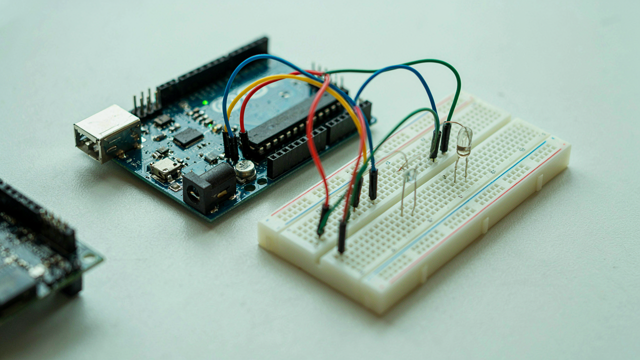
The Illusion Of Beginner Friendly Temperature Sensors
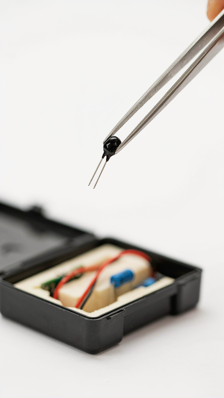
Why Easy Sensors Obscure Deeper Understanding
You want to avoid looking stupid, so you buy the sensor that promises “no soldering” and “plug and play.” Here’s the mechanism: convenience collapses your mental model. The DHT22 or DS18B20 hand you a number. You never learn what that number actually represents because the abstraction layer does the translation work for you.
Thermistors, thermocouples, and resistance temperature detectors all measure heat differently. A thermistor uses nonlinear resistance change. A thermocouple generates voltage from a junction of two metals. Each one teaches you how temperature sensing actually works. When you skip this layer and jump straight to a prepackaged sensor, you build projects, not understanding. You can’t troubleshoot anomalies you don’t comprehend.
The Cost Of Convenience Limited Data Insights
The common advice says “use a DHT22 because it’s easy.” That’s incomplete. What’s actually happening is you’re trading measurement precision and data density for speed. A DHT22 gives you one reading every two seconds maximum. It has a tolerance of plus or minus three percent. That’s acceptable for a room temperature display. It’s garbage for detecting thermal drift in a greenhouse or monitoring equipment degradation.
When you hook a raw thermistor to an Arduino ADC pin, you capture the analog signal directly. You control the sampling rate. You set your own calibration curve. You see the noise in the system instead of having it filtered away invisibly. The sensor itself becomes a learning tool. Your code must handle the conversion math, the linearization, the error correction. That work is where real knowledge lives.
Decoding Arduino Temperature Sensor Data: Beyond Raw Readings
Why Your Readings Lie Without Calibration
You want accurate data so you stop second-guessing your project. Here’s the mechanism nobody states plainly: raw analog values from a temperature sensor mean nothing until you map them to a known physical reality. That mapping is calibration. An Arduino reads voltage, not temperature. The sensor outputs voltage based on temperature, but the relationship drifts with component tolerances and aging. Without calibration, you’re reading numbers that feel precise but carry systematic error baked in from the factory.

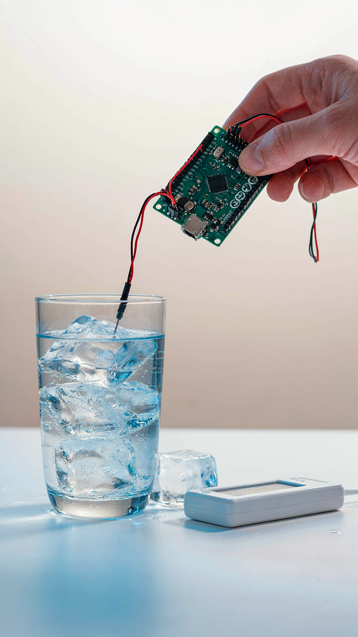
Calibration works by taking known reference temperatures and recording what voltage your specific sensor outputs at each point. The two-point method dominates because it’s fast and effective: measure your sensor’s output at ice water (0°C) and boiling water (100°C), then calculate the linear relationship between raw value and actual temperature. This compensates for your particular sensor’s offset and slope. Store these calibration constants in your Arduino code and apply them every time you convert a reading. The alternative, trusting the datasheet values, guarantees you’ll chase accuracy problems that don’t exist in your sensor but in your assumptions about it.
Drift, Noise, And What Actually Matters
Electrical engineers borrowed the signal-to-noise ratio concept from communications theory, and your temperature sensor operates on the same principle: the signal is the real temperature change you’re trying to measure, the noise is everything else muddying that signal. Noise comes from three sources: power supply ripple bleeding into your analog input, self-heating from the sensor drawing current, and quantization error from the Arduino’s 10-bit ADC resolution. Most beginners panic about the wrong one.
Quantization error is real but small: a 10-bit ADC reading temperatures 0 to 100°C produces roughly 0.1°C steps. Self-heating matters only if your sensor draws high current or sits in isolation without thermal contact to what you’re measuring. Power supply noise is the actual culprit in most amateur setups. Solve it by decoupling: place a 0.1 microfarad ceramic capacitor as close as physically possible to your sensor’s power pins, running another capacitor to ground near the Arduino’s analog input pin. Then average your readings in code. Take ten samples with 10 milliseconds between each, sum them, divide by ten. This kills 90 percent of jitter without adding latency that matters in most applications. The mechanism is simple: noise exists across frequencies, averaging eliminates the high-frequency components your project doesn’t care about anyway.
The Sensor Stratagem: Selecting The Right Tool, Not Just Any Tool
What Temperature Sensors Actually Do
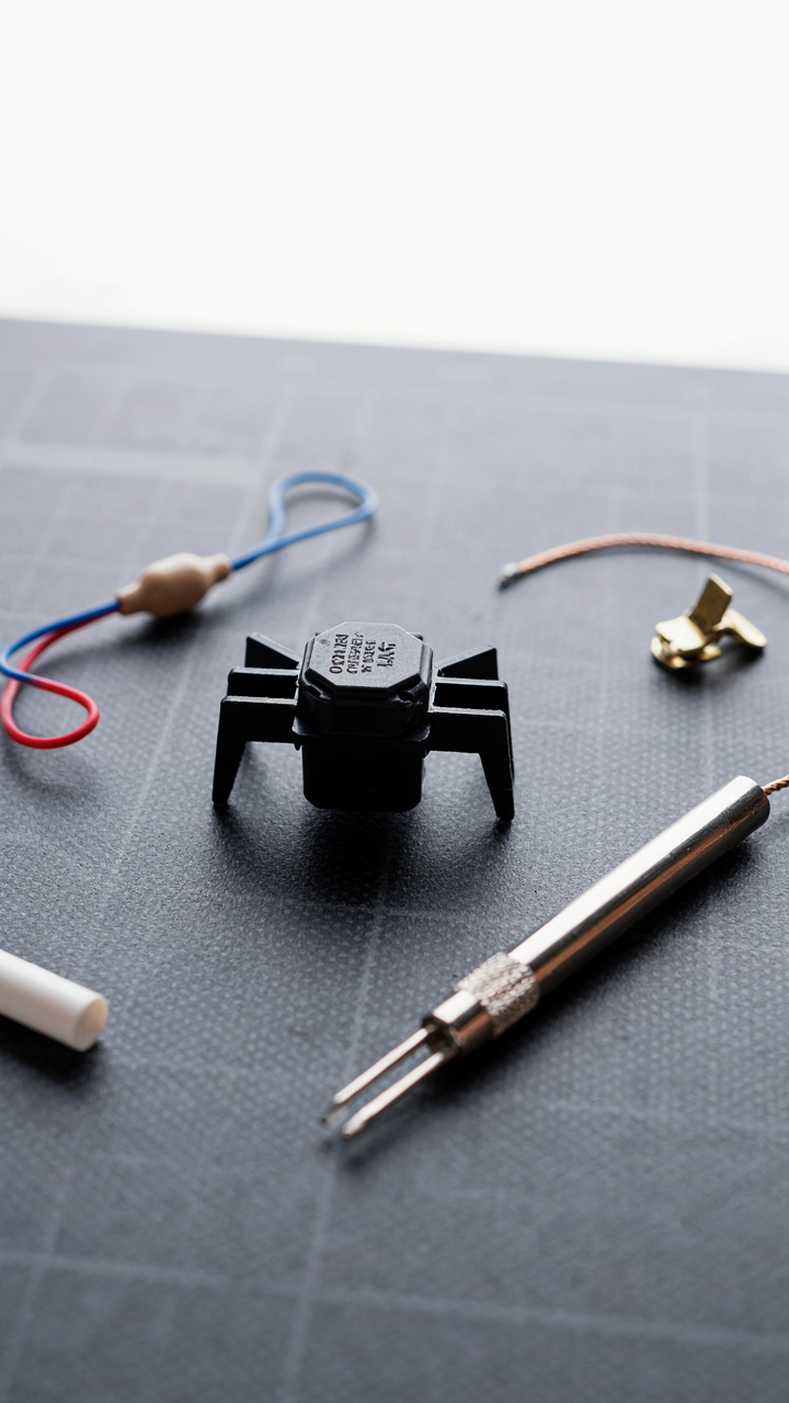
You’re worried you’ll pick wrong and waste money on hardware that doesn’t work for your project. Here’s the mechanism: every temperature sensor converts heat into a measurable electrical signal, but the physics changes the signal differently depending on sensor type. The conversion method determines accuracy, speed, cost, and how hard your Arduino has to work. Pick the wrong one and you’re not just throwing money away, you’re building friction into every line of code you write after.

Temperature sensing in electronics mirrors signal transmission in communications engineering. Both require you to encode information (temperature data in one case, a message in the other) into a format your system can read. A thermistor encodes temperature as resistance change. An RTD encodes it as resistance change too, but predictably and over wider ranges. A digital sensor like the DS18B20 encodes it as a serial data packet your Arduino reads directly. Understanding the encoding mechanism matters more than memorizing specs.
The Four Temperature Sensor Types You’ll Actually Encounter
- Thermistor (NTC or PTC): Resistance changes nonlinearly with temperature. Cheap, fast response, but requires calibration and math. Most hobbyists start here because they cost under a dollar.
- RTD (Resistance Temperature Detector): Resistance changes linearly with temperature. Stable and accurate but slower and requires a current source. Industrial standard for a reason.
- Thermocouple: Two different metals create voltage when heated. Handles extreme temperatures (up to 3000°C) but needs cold junction compensation and amplification. Overkill for Arduino beginners.
- Digital Sensor (DS18B20, DHT22): Built-in conversion and communication protocol. No calibration needed. One or two wires to your Arduino. Slower update rate but eliminates math headaches.
- Analog IC Sensors (LM35, TMP36): Linear voltage output proportional to temperature. Simple to read but less accurate than digital alternatives. Good for learning, poor for production.
The wrong choice doesn’t just cost money, it costs time debugging nonlinear equations or waiting for slow sensors. Your project’s constraints dictate the sensor. Temperature range needed, response speed required, accuracy tolerance, and power budget all eliminate options before you even look at price.
Match Sensor To What Your Project Actually Demands
Your application isn’t generic, so stop treating sensor selection like it is. A greenhouse monitor needs stability over weeks, not speed. A thermal warning system needs response time under one second. A data logging project can tolerate 30-second delays. Write down these three numbers for your project right now: maximum temperature you’ll measure, minimum temperature, acceptable margin of error. Then write response time needed in milliseconds. These four constraints eliminate most options immediately.
The DS18B20 dominates Arduino projects because it solves the wrong problem elegantly. It’s convenient, accurate to 0.5°C, and needs minimal code. But it only updates every 750 milliseconds at full resolution. If you need readings every 10 milliseconds, a thermistor with analog input beats it despite more complex math. If you need 0.1°C accuracy in a stable environment, an RTD with a Pt100 element and proper signal conditioning leaves both behind. Constraint-driven selection eliminates guessing. Measure first, select second, code third.
Integrating Arduino Humidity Sensor: The Environmental Nexus
Why Temperature And Humidity Move Together
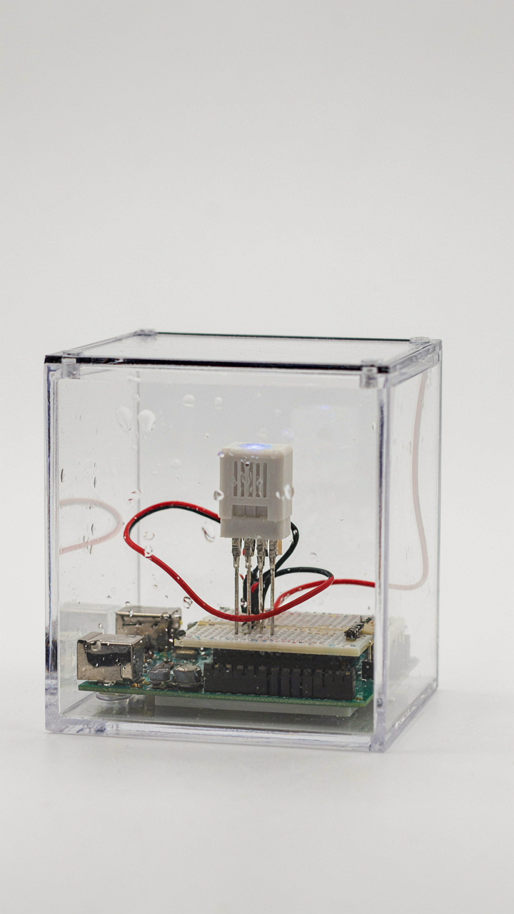
You want this section because you think adding humidity will make your project look more sophisticated. It won’t. But here’s what actually matters: temperature and humidity operate as a coupled system in thermodynamics. Think of it like signal and noise in electrical engineering—they’re distinct forces, but one distorts your reading of the other. Air temperature and moisture content interact. Warm air holds more water vapor than cold air. When you measure only temperature, you’re missing half the mechanism that determines how your sensor environment actually behaves.

Most Arduino tutorials skip this because it’s easier to ignore. Your DHT22 sensor reads both values simultaneously, but beginners treat humidity as optional decoration. The real mechanism: temperature sensors drift in accuracy when humidity fluctuates rapidly. High humidity causes condensation on the sensor element. This changes the surface properties that your thermistor or digital sensor relies on to calculate temperature. You need humidity data not to impress anyone, but to validate whether your temperature readings are trustworthy or corrupted by environmental moisture.
Sensor Fusion For Actual Environmental Truth
Combined sensor data reveals what single measurements hide. Your DHT22 outputs both temperature and humidity on one signal pin. When temperature rises 10 degrees but humidity drops from 70 to 40 percent, that’s a dry heat event. Your system responds differently than it would to 10 degrees of humid heat. The two readings together tell you the actual state of air. Separate them, and you’re working with incomplete information.
Wire the DHT22 data pin to Arduino pin 2. Read both values in the same loop iteration. Store them as paired data points with timestamps. This is sensor fusion in practice: you’re not adding complexity, you’re eliminating blind spots. The mechanism is straightforward. Temperature alone means nothing without knowing the moisture content of the air around it. Your code samples both simultaneously because they’re environmentally inseparable, not because it sounds more advanced.
The Feedback Loop Protocol: Building An Arduino Temperature Controller Project
Why Your Sensor Needs To Act, Not Just Report
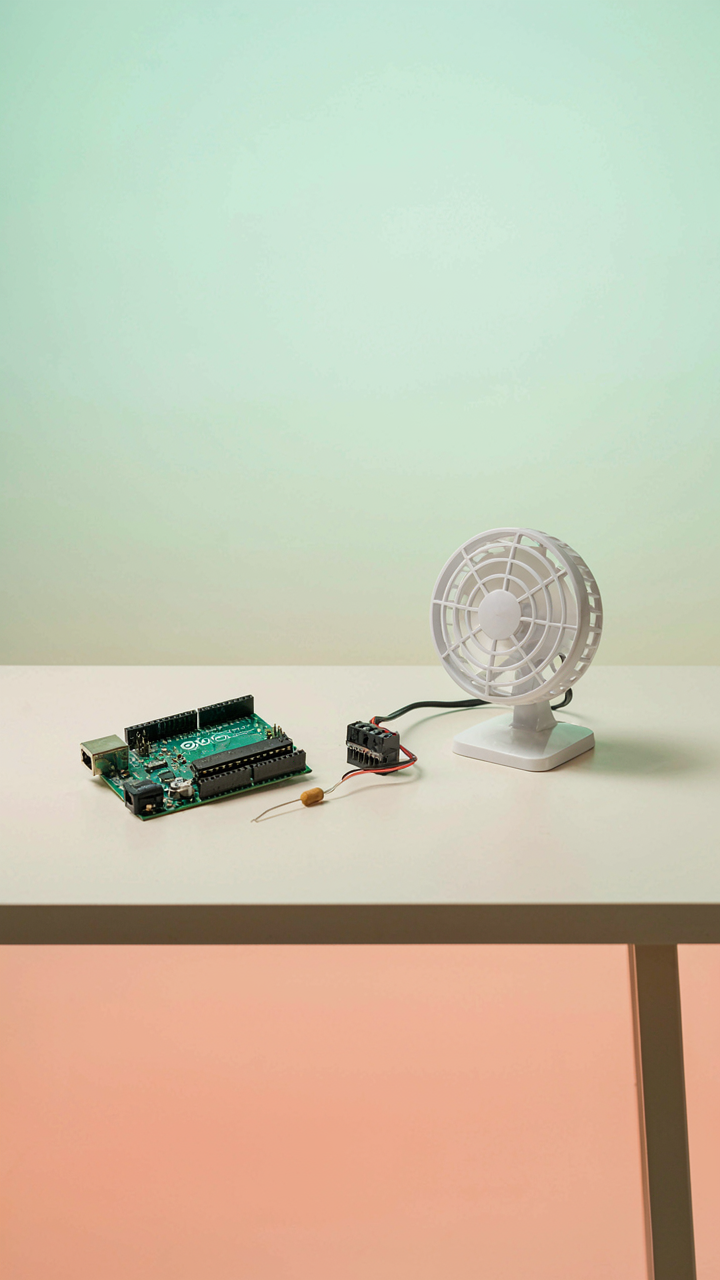
You want this project to feel like you built something that matters, not another sensor that prints numbers to a screen. The mechanism that actually matters is feedback: your Arduino measures temperature, compares it to a target, then triggers a physical response. This is cybernetics language. In control systems, we call this the error signal—the gap between where you are and where you want to be. Your temperature sensor becomes the measurement arm of that gap.

Most tutorials show you how to read a sensor. They skip the part that makes it functional. A real controller loops continuously. Read temperature. Calculate the difference from your setpoint. Adjust an output (heating element, fan, relay). Repeat. The sensor data only matters because it closes the loop and forces a decision. Without that action step, you have telemetry, not control.
Designing Output That Responds To Sensor Input
Don’t design your response after you wire the sensor. The sensor choice depends entirely on what you need to control. If you’re managing a small heater, you need faster response time, so a thermistor works. If you’re monitoring a room, a DHT11 or DS18B20 gives you the precision window you actually need. The design decision isn’t about sensor accuracy—it’s about how fast your control output needs to react to temperature swings.
Your Arduino pins can’t drive most heaters directly. You’ll route the sensor reading through a relay or MOSFET that switches real current. Set a threshold in code: if temperature drops below 22 degrees, activate the relay. If it rises above 24 degrees, cut power. The loop runs 10 times per second or faster. This prevents overshooting and keeps your environment stable. Your sensor tells the story; your output enforces the rule.
Arduino Code For Temperature Sensor: Writing For Control, Not Just Display

Reading Sensor Data Without Wasting Cycles
You want this section because you’re tired of code that works in theory but chokes when you scale it. The real mechanism here is sampling rate versus processing load. Your Arduino runs at a fixed clock speed, and every instruction costs cycles. Thermistors and temperature sensors don’t change state fast. You don’t need to read them every millisecond. Instead, implement a time-based sampling window using millis() to read the sensor every 500ms or 1000ms depending on your application.

Efficient acquisition means you read the analog value once, store it in a variable, then process it only when the timer fires. Use analogRead() to grab the raw ADC value between 0 and 1023, convert it to temperature using the sensor’s datasheet formula, and store the result. The formula differs by sensor type: an LM35 outputs 10mV per degree Celsius, while a thermistor requires the Steinhart-Hart equation or a lookup table. Don’t recalculate the conversion every loop cycle. Calculate it once per sample interval, then let your main loop run unblocked.
Triggering Actions Based On Temperature Thresholds
Control logic borrowed from systems engineering: your sensor is the input, temperature bounds are your constraints, and your output devices are the actuators. Set a high threshold and a low threshold. When the sensor reading crosses the high threshold, activate cooling. When it drops below the low threshold, deactivate it. This prevents oscillation where relays or fans toggle on and off constantly. You need hysteresis, not just a single setpoint.
Use an if-else structure with two separate conditions and a state variable to track whether cooling is active or inactive. If temperature exceeds 30 degrees and cooling is off, turn on the relay or fan and set a flag to true. If temperature drops below 25 degrees and cooling is on, turn it off and set the flag to false. Temperatures between 25 and 30 do nothing, which is your deadband. Write the relay control to a digitalWrite() pin, and log the state change with a timestamp so you can debug behavior later.
Connecting The Dots: How To Connect Temperature Sensor To Arduino, The Right Way
The Noise Problem Nobody Names
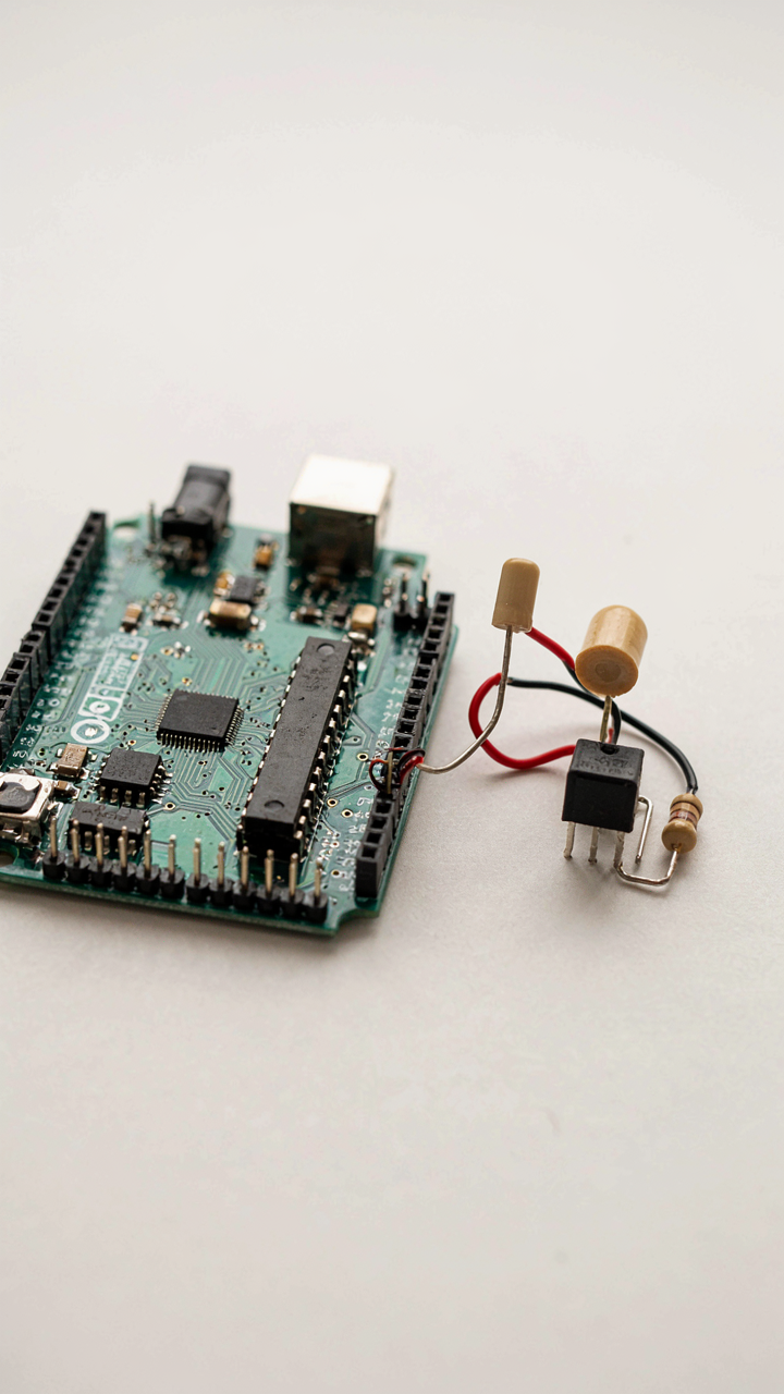
You want your readings to look clean in the serial monitor. That’s the real reason you’re reading this section. Here’s what actually happens: temperature sensors read analog voltage, and that voltage travels through wires that act as antennas. Every power supply hum, every switching transition in your circuit, every radio wave nearby couples into those wires as noise. Electrical engineering calls this electromagnetic interference. Your temperature sensor is a antenna that picks up garbage before the Arduino’s analog-to-digital converter samples it.

The mechanism is simple. Shorter wires mean less surface area for noise to couple onto. Shield the sensor wire with grounded metal braid if your runs exceed six inches. Better yet, run the sensor wire away from power lines and switching components like the DC jack or relay modules. Place a 100 nanofarad ceramic capacitor between the sensor output and ground, right at the sensor itself. This bypasses high-frequency noise directly to ground before it reaches the Arduino input pin. This single capacitor eliminates more noise than any code fix ever will.
Voltage Stability Determines Accuracy
The Arduino’s analog reference voltage is how it converts voltage to temperature. If your power supply sags when the microcontroller draws current or when you plug in USB, the reference voltage drifts, and so does every reading. Most beginners skip this and wonder why their sensor reads different values depending on what else is running on the board.
Run the sensor’s power through a separate low-dropout voltage regulator if you’re using a thermistor or an analog sensor like the TMP36. Don’t power it directly from the Arduino’s 5V pin. Use a 4.7 microfarad electrolytic capacitor on the regulator’s output to absorb supply ripple. If you’re using an I2C digital sensor like the BME280, the same rule applies but the tolerance is tighter because digital sensors integrate the reading over time. One stable power rail beats noise filtering every time.
Beyond Hobby: Temperature Sensor For Electronics And Industry

When Prototype Becomes Liability
You want to look competent in front of people who write checks. That’s the real reason you care about moving from Arduino breadboard to industrial deployment. The mechanism is simple: hobbyist sensors drift, fail without warning, and destroy confidence. Industrial applications demand predictability. A DHT22 drifts 2 to 5 degrees Celsius over time. A DS18B20 holds tolerance but lacks redundancy. Neither works when your system can’t fail.

The shift from hobby to industry isn’t about buying expensive sensors. It’s about accepting that your measurement must be defensible. In manufacturing, pharmaceutical storage, or HVAC systems, a single bad reading triggers recalls, regulatory fines, or safety violations. Your Arduino must move from “does it work sometimes” to “does it work within spec every single time.” This means calibration protocols, error checking, and redundant measurement paths built into firmware before you ship anything.
Tolerance, Calibration, And The One Thing Everyone Skips
Redundancy isn’t glamorous, so nobody talks about it. Every industrial temperature sensor setup uses at least two independent measurements running in parallel. The mechanism here borrows from control systems engineering: a setpoint is your target range, feedback is your sensor reading, and error correction is what happens when they disagree. A single DS18B20 reports 22.5 degrees. A second DS18B20 reports 22.8 degrees. Your code flags this deviation, logs it, and either averages the reading or triggers an alarm depending on your tolerance window.
Your Arduino code must include calibration data stored in EEPROM before deployment. Record your sensor’s actual output against a known reference (a calibrated lab thermometer) at three points across your operating range. Enter those correction factors into memory. This single step eliminates systematic error that would otherwise haunt you in the field. Without it, you’re trusting factory calibration, which assumes your sensor was stored correctly and hasn’t drifted since manufacture.
The Unspoken Truth About Arduino Projects: They Demand Systems Thinking
Components Don’t Work Alone
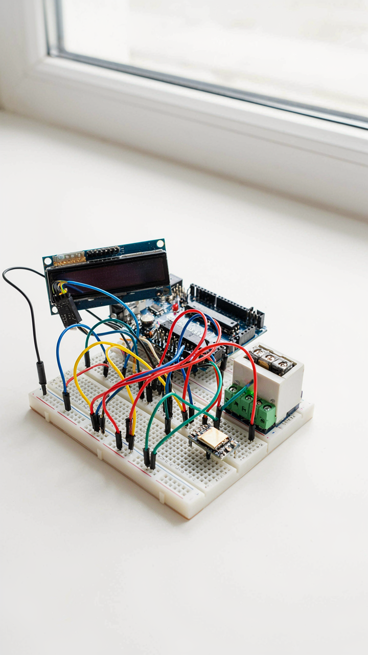
You want to feel like a maker, like you’ve built something real. But that’s exactly why most Arduino temperature sensor projects fail after two weeks. A thermistor wired to an analog pin isn’t a system yet. It’s an isolated input waiting to be ignored. Systems thinking from engineering demands you map feedback loops, not just connections. Your temperature sensor feeds data to the microcontroller, which processes it, outputs results, then influences the environment it measures—that’s the loop.

The difference between a dead project and a live one is whether every component has a clear role in achieving an outcome. Your DHT22 sensor collects humidity and temperature. Your Arduino processes both values. Your display shows results. Your relay triggers a fan or heater based on thresholds. Remove any piece and the system breaks. That’s the check. If you can’t explain why each component exists, you don’t have a system yet.
The Maintenance Protocol That Actually Works
Most people abandon projects because they never planned for drift, calibration failure, or power loss. That’s lazy design, not bad luck. Thermal sensors drift over time. Your DHT22 might read 0.5 degrees off after six months of continuous operation. You need a calibration schedule, not wishes. Document your initial baseline readings against a known reference thermometer on day one. Record it. Then run the same check every three months. If drift exceeds your tolerance threshold, you recalibrate or replace the sensor.
The concrete action: Build a log file into your code. Every sensor reading gets timestamped and stored to EEPROM or an SD card. This creates a historical record that shows degradation patterns before they wreck your data. Set a backup power system if temperature monitoring matters for safety. A small battery-backed RTC (real time clock) keeps your Arduino running through brownouts. When power returns, your system resumes without losing the timestamp chain. This transforms an experiment into infrastructure.
The Real Obstacle Isn’t Code Or Circuits, But Your Reluctance To Build Systems, Not Just Components

Most people wire a temperature sensor, watch it work once, then abandon it. They built a component, not a system. Real builders connect that sensor to logging data, trigger alerts, or control something based on what it reads. That’s where the skill lives. Stop treating Arduino projects as finished products. Treat them as the first domino in a chain you actually build. Today, grab your sensor and add one output that does something when the temperature changes. Nothing teaches you faster than building the next layer instead of admiring the first one.