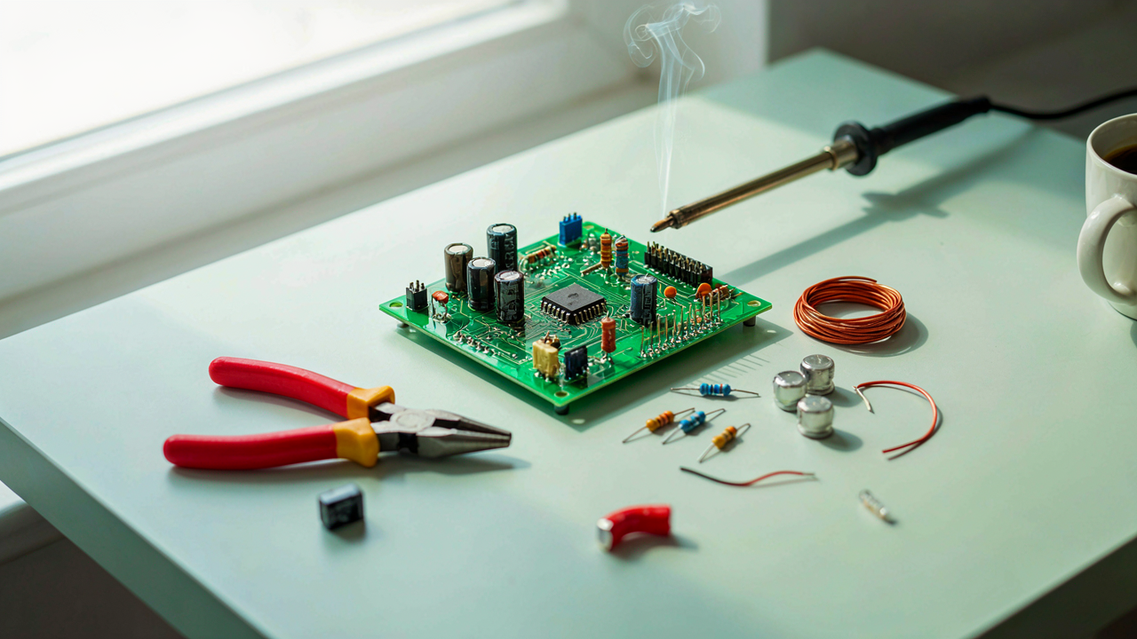
The Illusion Of The “Basic” DIY Audio Amplifier Kit

What A Kit Actually Hides From You
You want to believe a kit makes this simple because you’re afraid the real work is harder than you thought. Here’s the mechanism: a kit is a permission slip, not a guarantee. The manufacturer pre-selects components and assumes conditions you don’t control. Your power supply quality, your soldering temperature, your speaker impedance, your room acoustics, your component tolerances from the factory run—none of these live inside the box. The kit succeeds only if your real-world setup matches the invisible assumptions baked into the design.
Component matching is where kits expose their limits. Resistors marked 10k ohms actually land between 9.7k and 10.3k in tolerance. Capacitors drift. Transformers vary. A kit manual shows a circuit diagram, not the margin for error. When you stack five or six components with stacked tolerances, your amplifier’s frequency response, gain, and bias point shift away from spec. The instruction sheet never calculates this cumulative drift because it assumes factory-controlled conditions you won’t have at your workbench.
Variables The Manual Will Not Tell You
Think of this like ballistics: the projectile path depends on powder charge, barrel temperature, and air density—none printed on the bullet. Your amplifier’s behavior lives in the gaps between components, not in the components themselves. Output impedance matching, for example. A kit tells you to use an 8-ohm speaker but never explains that a 6-ohm speaker loads differently, changing your damping factor and bass response. That’s not in the manual because it falls outside the kit’s assumed operating range.
Thermal stability breaks most beginner builds. Transistor gain changes with temperature. Heat causes capacitor values to drift. Your room temperature today differs from tomorrow. Bias current, set once during assembly, drifts within hours as the circuit warms up. The kit assumes you understand this happens and plan for it. You don’t. No beginner measures idle current after the amp reaches thermal equilibrium. Measure your bias point at five-minute intervals for the first thirty minutes of operation, then every ten minutes until the reading stabilizes.
Deconstructing The Power Amplifier Circuit Diagram: More Than Wires
Why Each Component Behaves Like A Living System
You want to understand amplifier schematics so you can feel smart enough to build one. Here’s what actually matters: the circuit diagram is not a map of isolated components. It’s a system where each part changes how every other part performs. Treat it like ecology, not plumbing. In ecology, removing one organism destabilizes the entire habitat. A resistor doesn’t just resist current in a vacuum. It interacts with capacitors nearby, voltage supplies, and transistor bias points to create a working whole that either amplifies cleanly or produces garbage.

Most beginners read a schematic and think “wire connects A to B, B to C.” They miss the load impedance the amplifier sees, the feedback paths that stabilize gain, and how component tolerances compound across stages. A 5% error in one resistor cascades downstream. The preamp stage feeds the driver stage feeds the power stage. Each one depends on what comes before it. Change one capacitor value by 20% and your frequency response shifts noticeably. The circuit is a conversation between components, not a checklist.
Heat Distribution Determines Actual Lifespan
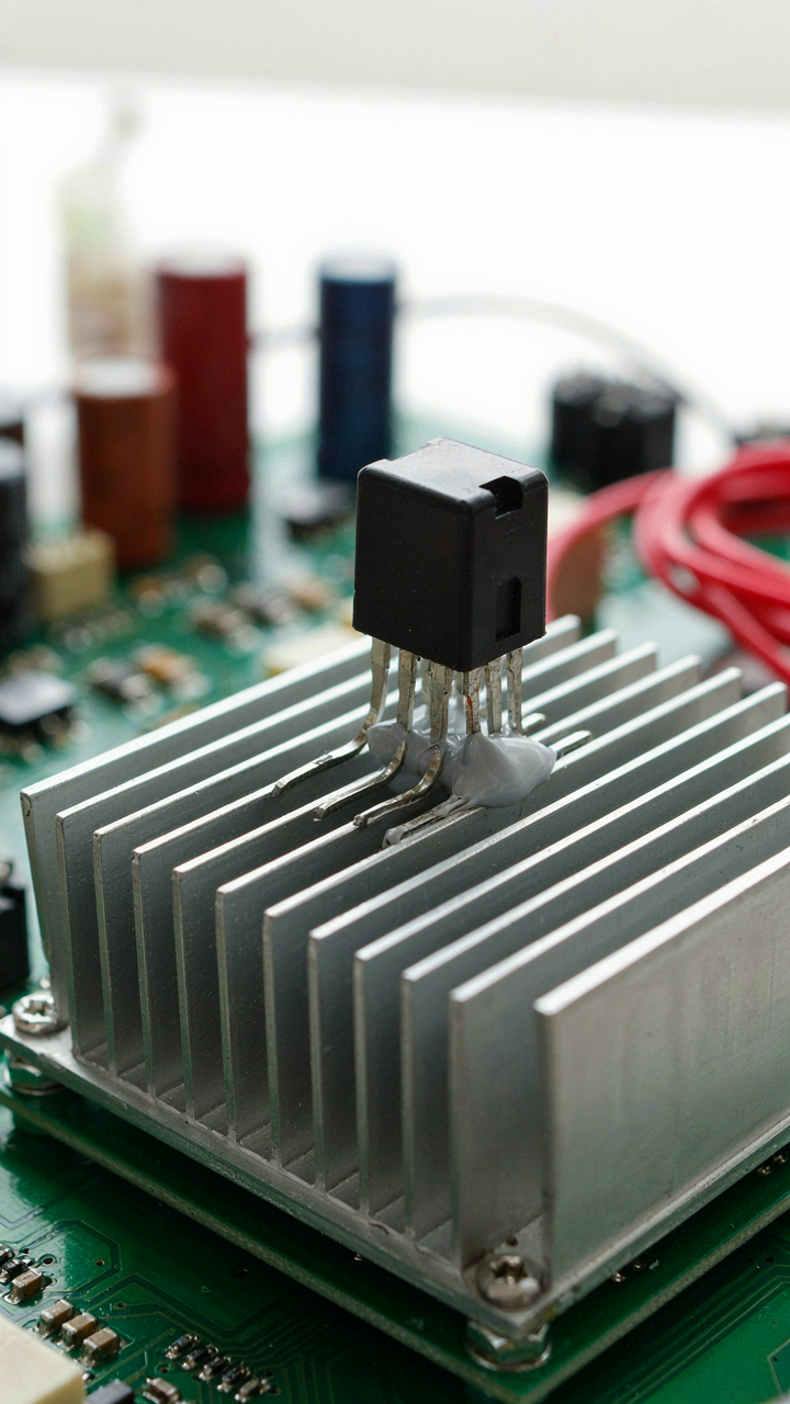
Thermal dynamics aren’t optional extras you consider after assembly. They’re the reason amplifiers fail. A transistor rated for 100 watts will die fast if mounted directly to a case with no heatsink, even though the circuit diagram never mentions temperature. Physics tells us that all semiconductors degrade faster at higher junction temperatures. A 10-degree Celsius rise in a transistor’s internal heat cuts its lifespan roughly in half. Your schematic shows what current flows, but thermal management determines whether the amplifier survives five years or five months.
Component degradation follows this rule: electrolytic capacitors dry out faster when warm. Output transistors lose gain and develop leakage paths when they run hot. Even resistors drift from their nominal value under sustained heat. The real limiting factor in a DIY build isn’t usually the circuit topology. It’s whether you mounted power transistors to adequate heatsinks with thermal paste rated for the job. Measure the case temperature during full-power operation. If the heatsink is too hot to touch comfortably for ten seconds, your components are aging ahead of schedule.
The Chaos Theory Of Troubleshooting Method For Diy Audio Amplifier Circuit

One Failed Component Cascades Into Ten Problems
You want a framework that makes you look competent when your amp fails. Here’s what actually happens: in amplifier circuits, one small failure upstream destroys the diagnosis downstream. Physics calls this sensitivity to initial conditions. In your amp, it’s what happens when a single capacitor leaks and corrupts your voltage rails for the entire signal chain.

Most troubleshooting advice tells you to test everything linearly from input to output. That’s incomplete. A failed coupling capacitor upstream won’t show up as a broken component when you measure it in isolation. It shows up as distortion three stages later, forcing you to chase ghosts in your preamp section while the real culprit sits undetected. The mechanism is voltage drift. You fix it by mapping signal flow backwards from the symptom, not forwards from the input.
Think In Supply Lines, Not Components
Military logistics separates supply lines from the fighting itself because one broken supply line collapses the entire operation. Your amplifier topology mirrors this structure. Your power supply rail is the supply line. Your output stage, driver stage, and preamp are dependent positions. When the rail voltage sags under load, every stage starves simultaneously, but symptoms appear unrelated across different sections.
Stop testing components in order. Test the power supply rail voltage first under load, then work backwards to the transformer and rectifier stage. If rail voltage holds steady but your output is weak, move to the driver stage. If driver stage looks clean but output fails, isolation mode reveals that your output transistors are oscillating at a frequency your meter cannot catch. The hierarchy of diagnosis saves hours: power delivery first, then signal integrity, then component function.
Beyond Stereo: How To Build A 5.1 Amplifier And The Scalability Fallacy

Complexity Exponential, Not Linear
You want 5.1 because stereo feels incomplete. That’s not a technical reason. It’s status. Here’s what actually happens: adding channels doesn’t scale like adding speakers. Amplifier design operates under exponential constraint, borrowed from systems engineering, where each new output path multiplies thermal load, power supply demands, and noise floor interaction rather than adding them. Two channels demand one power transformer. Five channels demand a transformer sized for peak simultaneous draw across all stages, not the sum of individual channels.

The real trap is thermal management. A stereo amp dissipates heat in one location. A 5.1 amp spreads heat across multiple output stages competing for the same heatsink real estate or requires separate heatsinks that create layout problems in a chassis. You can’t just replicate a proven stereo circuit five times and expect stability. Each output transistor generates bias heat that affects the next stage’s performance. Temperature coefficients compound. Hum and crosstalk between channels become engineering problems, not afterthoughts.
The Hidden Costs Of Multichannel Expansion
Everyone talks about needing five amplifiers. Nobody talks about the power supply becoming your actual project. A stereo amp might run off a 500VA transformer. A 5.1 amp needs 1500VA minimum, often higher if you’re driving passive speakers at real SPL. You’re not just buying more transformer capacity. You’re buying regulation headaches. More capacitance means longer charge cycles. More rectification stages mean more complexity in your power supply design. A weak power supply kills multichannel performance faster than anything else because each channel steals current from its neighbors under dynamic load.
The cost hierarchy inverts at multichannel scale. Speaker cables and interconnects become critical where they were forgiving in stereo. Ground planes shift from optional to mandatory. Component tolerances that mattered at 0.1% in a two-channel build now create audible channel imbalance at 5.1. You’re also adding a subwoofer amplifier, which means a second build entirely with its own power supply, crossover, and integration challenges. Most builders discover too late that the actual expense is testing and tuning equipment to verify your five channels actually work together without phase issues or frequency response anomalies that only show up at volume.
The Unspoken Truth Of Audio Amplifier Circuit Ideas: Signal Integrity As Your God
Why Noise Kills Your Amp Before It Starts
You’re building this amp because you want clean sound. But you really want proof that you did something right. Here’s the mechanism: noise floor is determined by every component touching your signal path, and most builders ignore it completely. A 10 microvolt noise spec sounds invisible until you realize your preamp stage is generating 50 microvolts. The math doesn’t lie. Your amp will never sound better than its worst weak point.

Noise doesn’t come from nowhere. It emerges from thermal activity in resistors, shot noise in transistors, and coupling capacitors doing their job poorly. Common advice says use metal film resistors and move on. That’s incomplete. The real control is understanding that noise compounds across stages. Your input stage noise gets amplified by every subsequent stage, so a noisy first transistor ruins everything downstream. Choose your first active component like your life depends on it, because your signal integrity does.
Grounding Schemes And Electromagnetic Interference
Think of grounding like military supply lines in a conflict zone. Bad logistics collapse the entire operation. Electromagnetic interference operates the same way: voltage divides through impedance, and a poor ground path is high impedance. Most DIY builders treat grounding as an afterthought, which is why their amps hum at 50 or 60 hertz and pick up radio stations. Ground isn’t a dump for stray voltage. Ground is your signal reference, and if it’s floating or noisy, every stage interprets signals incorrectly.
- Star Grounding: Connect all ground returns to a single point at the power supply, not daisy-chained through the circuit board. Prevents ground loops and voltage dividers that create hum.
- Twisted Pair Signal Cables: Route audio inputs as twisted pairs to reject magnetic field coupling from adjacent power wires and transformers.
- Ground Plane Layers: If using a PCB, dedicate an entire copper layer to ground. This lowers impedance and provides a low-resistance return path for high-frequency signals.
- Shielded Enclosure Design: Use grounded metal chassis and shielding around input stages, especially preamp circuits running at millivolt levels.
- Power Supply Filtering: Place bulk capacitors near power entry, then smaller film capacitors near each active device to suppress supply noise before it contaminates signal stages.
Your grounding scheme determines whether you hear music or noise floor. Build a proper star ground point at the power supply using a single thick copper bar or bus. Every ground connection joins there, not scattered across your PCB. Route signal cables away from power cables by at least two inches, or use shielded cables grounded only at the input stage end. The physics is nonnegotiable: electromagnetic fields couple into loops, and eliminating loops eliminates coupling.
Amplifier Design: The “Anti Fragile” Approach To Component Selection

Buy Better Parts Than Your Design Requires
You want to feel like you made a smart decision. Here’s the mechanism: you’re buying a kit where the manufacturer specs components at minimum threshold, and you’re treating that as permission to do the same. It isn’t. In biology, antifragility means a system gains from disorder. Your amp gains from headroom. A power supply rated for 10% more than your circuit demands doesn’t just survive stress, it performs better under it. Electrolytic capacitors degrade. Output transistors age. Resistor tolerances drift over time. Build in margin and you compress the failure curve by years.

The common advice is to match component values exactly to the schematic. Wrong. The schematic represents one point on a spectrum of viable designs. A transformer rated 20% hotter than needed absorbs thermal spikes without saturating. Film capacitors rated double the voltage you’re actually running won’t fail at the moment your wall power surges. This isn’t overkill, it’s probability management. Your goal isn’t to make the amp work once in the lab. It’s to make it work reliably in someone’s living room for a decade through power fluctuations you can’t predict.
Weak Spots Most Kits Hide
Output transistors die first because they handle current peaks and temperature swings that other components never see. Electrolytic capacitors fail because internal resistance climbs with heat and age, and most kits use the cheapest Japanese stock. The power supply transformer can overheat if it’s wound too tight or uses thin wire gauge. Input coupling capacitors dry out and degrade, collapsing your low end. The output protection relay contacts oxidize and fail silently. Finally, solder joints on high current paths cold solder or crack from thermal cycling.
- Output Transistors: Mount on heatsinks even if the schematic doesn’t require it. Thermal stress kills them faster than electrical stress. Use matched pairs from reputable manufacturers, not salvage bins.
- Electrolytic Capacitors: Replace all stock capacitors with audio grade units rated 50V minimum even if the circuit runs at 35V. Use Nichicon or Panasonic, not unmarked surplus.
- Power Supply Transformer: Verify the gauge of primary and secondary windings before assembly. Undersized wire creates heat and DC resistance that throttles output power.
- Input Coupling Capacitors: Use film capacitors for audio path coupling, never electrolytics. They don’t dry out and maintain frequency response across decades.
- Solder Joints On Output Stage: Use 60/40 or lead free solder with proper flux. Cold solder creates intermittent failures that emerge after five hours of use, not five minutes.
The upgrade pathway is simple: identify which components sit in the highest stress zone, then move up one tier in rating or quality. Your amp doesn’t need exotic parts. It needs parts that work when the conditions get hostile. Start by replacing the power supply capacitors and output transistor heatsink. Measure the transformer temperature under full load. If it exceeds 60 degrees Celsius after one hour, replace it with a unit rated 50% higher in VA. This is how you build systems that outlast the hype cycle.
Electronic Schematics: Reading Between The Lines For True Mastery

What The Symbols Actually Mean
You want to feel competent without actually understanding the machine. A schematic isn’t a picture of what something looks like—it’s a language describing how energy moves. Learn the symbols first because they’re not arbitrary. A resistor looks like a zigzag because it was originally drawn to show physical obstruction. A capacitor is two parallel lines because that’s what it actually is. The symbol teaches the function.

Every symbol compresses a rule. Diodes point in the direction current flows. Transistors show which terminal controls the gate. Ground symbols repeat because they’re the reference point everything else measures against. Reading a schematic means recognizing that the designer chose each symbol to encode a specific behavior. Skip symbol mastery and you’re decoding without a key. Spend an hour on this. It compounds.
Voltage Rails And The Current’s Real Path
Physics calls this topology—the spatial arrangement that determines system behavior. Your amplifier uses voltage rails like a highway system uses routes: current doesn’t decide where to go, the rails decide. Most learners trace wires and miss the core mechanic: positive and negative rails are not just entry and exit points, they’re the structural skeleton that determines what every component can do.
A component mounted between +12V and ground can only pull current downward through the path you provide. The rails constrain possibility. Trace every component to both its power source and ground, not just one. You’ll see that coupling capacitors block DC but pass AC, output transformers handle impedance conversion, and feedback networks return portions of output to input. The path layout determines gain, frequency response, and distortion character. Map this physically on paper before breadboarding anything.
The “DIY Amplifier” Myth: Why Your First Build Will Fail (and Why It Should)

Failure As Signal, Not Setback
You’re reading this because you’re afraid your first amp won’t work, and you want permission to skip that part. Here’s the mechanism: failure is data. In control systems engineering, engineers deliberately introduce errors to map system behavior under stress. Your blown component, your hum, your distortion at half volume—these aren’t obstacles. They’re direct readouts of what your circuit actually does versus what you assumed it would do.

Most beginners treat failure as proof they shouldn’t have tried. Wrong. Failure is the only reliable teacher because it forces you to trace causation backward. A dead output transformer tells you something about your bias point. Oscillation at high frequencies tells you your feedback loop has phase shift you didn’t account for. You cannot learn this from a schematic. The circuit only teaches when it breaks.
Build, Measure, Adjust, Repeat
The standard advice here is “start simple.” That’s incomplete. You need a protocol, not a platitude. Begin with a single-stage amplifier using proven topology—a 12AX7 preamp stage into a power amp output, or a straightforward 6V6 single-ended design. Build it. Measure the gain with a signal generator and multimeter. Measure the frequency response. Measure the output impedance. Document everything. Then deliberately change one component—a coupling capacitor value, a resistor in the bias network—and measure again.
This isn’t perfectionism. It’s the only way to build intuition about how circuits respond to parameter changes. You’ll discover that your amp sounds thin because the coupling cap is too small, not because you’re “missing something.” You’ll find the hum comes from inadequate power supply filtering, not a mysterious design flaw. After three builds using this method, you stop needing schematics and start reading circuits. The mechanism is simple: iteration compresses learning time by forcing you to own every variable.
The Real Obstacle Isn’t The Circuit Diagram; It’s Your Assumption That Basic Means Effortless Mastery

Most people quit a DIY amplifier project because they expect competence to arrive instantly. It won’t. The actual barrier isn’t the schematic or the soldering iron. It’s your willingness to fail loudly and adjust without ego. Stop waiting for the “right time” to start. Buy a cheap kit today, break something, and actually fix it. The only people building amplifiers aren’t smarter than you. They just stopped pretending understanding comes before doing.