The Illusion Of The Dead Circuit: It’s Always Talking

No Signal Means Below Threshold, Not Absent
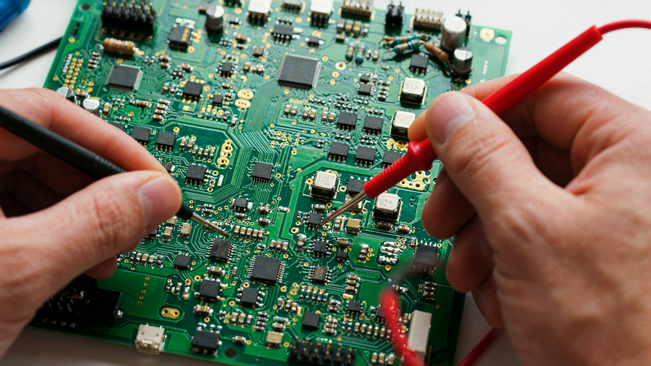
You want to believe the circuit is broken because broken is clean, final, and absolves you of looking harder. The mechanism is signal detection, borrowed from signal processing: a circuit only appears dead when its output falls below your instrument’s sensitivity floor. A multimeter set to 200V DC won’t catch millivolts. A scope with wrong coupling won’t see AC ripple on a rail. The circuit is transmitting. You’re just not listening.
Every node in a circuit outputs information. Voltage is present at nearly all points unless there’s a hard short or open. Current flows unless a path is severed. Noise exists on every rail. The practical move: match your measurement tool to the expected signal magnitude before declaring anything dead. Set the multimeter to the appropriate range. Use AC coupling on the scope if you’re hunting bias shifts. Check ground reference at the measurement point, not across the room.
Subtle Cues Cost More Than Dramatic Failures
Ignoring weak clues and hunting for the catastrophic failure is the expensive mistake. A rail at 4.8V instead of 5V looks fine until the logic threshold fails three hours into operation. A rising edge that’s 2ns slower than spec hints at a loading problem, but you overlook it chasing shorts. A capacitor that measures in-spec but has high ESR steals current without showing obvious distress. These signals are real. Missing them means you troubleshoot the wrong layer for weeks.
The protocol is direct: establish baseline performance first, then measure against it. Know what each node should be under normal load. Know the edge timing on clocks and critical signals. Know the temperature coefficient of that power supply. Document these baselines before anything fails. When a circuit misbehaves, compare actual to baseline, not to vague intuition or “should work” logic. The first deviation from baseline, however small, is your entry point. Follow it mechanically.
The “Probable Suspects” Fallacy: Ditch The Obvious First
Why Common Failures Distract From Root Causes
You want to feel competent fast. That’s why you reach for the obvious culprits first—a blown fuse, a loose wire, a dead battery. The mechanism is simple: your brain pattern-matches to the most frequent failures you’ve seen before, then stops looking. This is cognitive efficiency masquerading as troubleshooting. It fails because circuits don’t break the way your memory categorizes them. The most common symptom masks the actual failure mode ninety percent of the time.

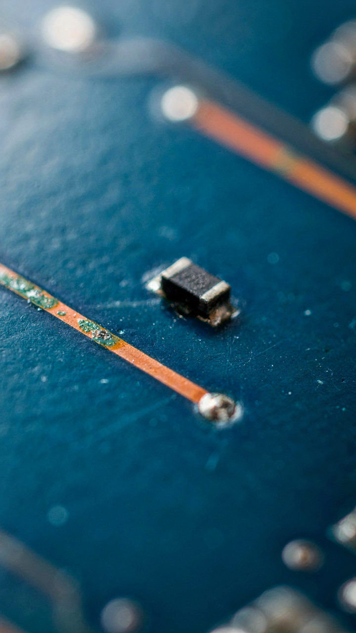
Classic troubleshooting advice tells you to “check the basics first.” This is incomplete. Checking basics is fine, but it’s not a substitute for understanding the circuit’s intended function. A dead component sitting next to a corroded PCB trace will produce identical symptoms—no voltage, no continuity. If you replace the component and ignore the corrosion, the circuit dies again in six months. You’ve treated the surface, not the system. Real troubleshooting means identifying which failure caused the symptom, not just which component could theoretically cause it.
Systemic Breakdowns Hide Behind Surface Symptoms
Borrowing from medicine: a fever is a symptom, not a diagnosis. The human body produces fever as a response to multiple root causes—infection, inflammation, immune reaction. The same principle applies to circuits. A short circuit at the output could mean a failed transistor, a shorted capacitor, a trace bridged by solder, or a design flaw that loads the output excessively. Each requires a different fix. Replacing components until the short vanishes wastes time and money. You’re medicating the symptom instead of treating the disease.
The real move is this: isolate the failure to a specific stage or component class before you touch anything. Use voltage measurements to confirm the circuit operates in stages. Does the power supply output correct voltage? Does the preamp stage amplify? Does the output stage deliver current? If one stage fails, the stages downstream show symptoms that belong to the upstream failure. You find the actual broken part by eliminating working sections, not by guessing. Stop replacing obvious components and start measuring the path of signal flow.
The Diagnostic Triage Protocol: Beyond Go/No Go

Segment The Circuit Into Testable Zones
You want to skip this step because it feels like wasted time when the circuit is already broken. Here’s what actually happens: you’re looking for the boundary between working and dead sections. That’s your failure point. Think of it like military supply lines—you find where the flow stops, not where it shouldn’t be. Most people test random components and call it troubleshooting. That’s noise.

Start from the power source and work forward in stages. Divide the circuit at logical break points: after the power supply, after major filtering, after the first amplification stage, before the load. Test voltage at each boundary. You’re building a map of what’s alive and what’s not.
- Power supply output: Verify DC voltage with a multimeter at the supply terminals before any components draw current.
- After filtering stage: Check for ripple voltage and confirm the filter capacitors are doing their job with minimal noise.
- Signal input node: Confirm the input signal exists and has the correct amplitude before it enters any processing stage.
- Between major stages: Test at the junction between preamp and power amp, or between logic and power sections, depending on circuit type.
- Load connection point: Measure voltage and current at the final output before the load pulls power to spot impedance mismatches.
The goal is binary: each zone either passes voltage forward or it doesn’t. Once you know which zone is dead, you’ve eliminated 80% of the circuit from suspicion. That’s efficiency. Now drill into that zone and repeat the process at smaller increments.
Follow Power Flow, Not Component Count
Everyone fixates on the complex parts because they look important. Audio circuits with multiple op-amps, power supplies with three voltage rails, digital boards with microcontrollers—these feel like the culprit. They usually aren’t. The mechanism here comes from power distribution: faults travel upstream from the load, not downstream from the source. A dead speaker doesn’t mean the amplifier failed. It means check what’s feeding the amplifier first.
Start troubleshooting at the power entry point and move toward the load. If the power supply rails read correct, move to the first stage. If that stage outputs signal correctly, the broken component is downstream. This order matters because a single fault point earlier in the chain will kill everything behind it, but a failed component later won’t affect upstream stages. You’ll find the root cause faster by following electrons, not chasing the most suspicious-looking part.
Mapping The Failure Domain: A Cartographer’s Approach To Electrical Engineering
Trace The Contagion Pattern First
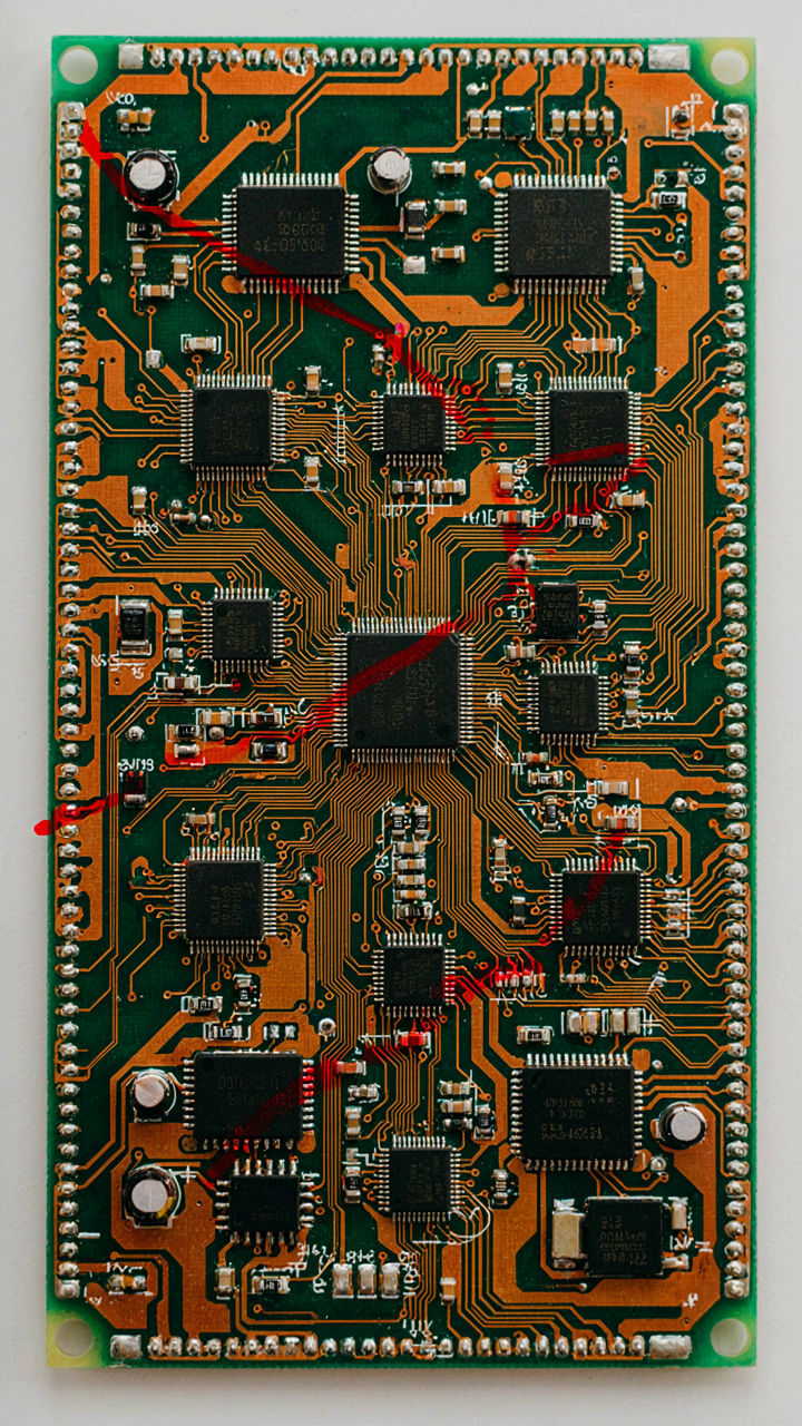
You want a systematic method so you look competent and stop wasting hours. Here’s what nobody says plainly: circuit failures spread like infection vectors. Epidemiology teaches us that disease doesn’t pop up randomly—it traces a path from source to host. Same with electrical failure. The failure originates at one point and propagates downstream. Your job is finding patient zero, not treating every symptom downstream.

Start at the power source. Verify voltage present. Then move forward one stage at a time, checking both voltage and current at each node. The moment you lose signal, you’ve found the contamination boundary. Everything before that point is clean. Everything after is suspect. This boundary is where the actual failure lives, not in the components that work fine on either side.
Redraw The Current Path As Plumbing
Current behaves like water under pressure. It takes the path of least resistance and stops flowing when blocked. Thinking of your circuit as a plumbing schematic clarifies what’s happening in ways a schematic alone won’t. If water won’t flow through a pipe, you check for blockages, breaks, or closed valves. Circuit diagnostics work the same way.
Map the physical path current must travel: from the positive rail through the load and back to negative. Draw this on paper if the circuit is complex. Identify where current actually flows versus where it should flow. Measure voltage at points along this path. A voltage drop tells you current is flowing through that section. No drop means current never arrived. This visual map reveals whether the problem is a broken path, a blockage, or something pulling current away before it reaches the load.
The Power Rail Predicament: Voltage Isn’t Everything
When Voltage Reads Fine But Current Can’t Flow
You want to believe the multimeter. A stable 5V on the rail means the power supply works, right? Wrong. You’re confusing a reading with a guarantee. The real mechanism: voltage is potential. Current is delivery. A power supply can maintain voltage under light load while collapsing under the actual load your circuit demands. Your multimeter’s input impedance is so high it draws almost no current, so it tells you nothing about what happens when real components turn on.

The distinction matters because this is where supply-side impedance becomes your enemy. Think of it like water pressure in a pipe: you can have perfect pressure at the source, but if the pipe narrows or clogs, nothing flows downstream. Your power rail has source impedance, trace resistance, and capacitor ESR working against current delivery. Measure voltage at the component that’s failing, not at the supply connector. The voltage drop between supply and load reveals the real problem.
Ripple And Noise Masquerade As Stability
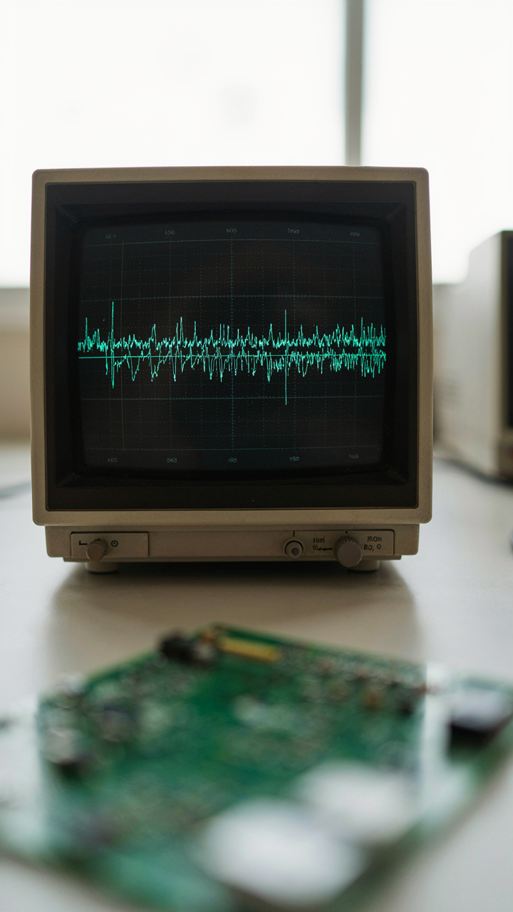
Most troubleshooters look at DC voltage and call it done. The common advice is lazy. Ripple, noise, and transient response are silent killers that a standard multimeter cannot see. An oscilloscope shows you the truth: the rail oscillates, overshoots, and rings. Components tolerate a narrow band. Push outside that band and logic fails, resets trigger, or ADC readings scatter.
Ripple comes from switching frequency and inadequate output filtering. Noise comes from high-frequency coupling, loop inductance, and poor layout. Transient response is how fast your supply reacts when load current changes suddenly. A digital system drawing 1 amp from an idle state creates a transient that your power delivery network must suppress in microseconds. If it cannot, the core voltage dips below the minimum threshold and the processor glitches. Measure the AC component at the load point with an oscilloscope set to AC coupling and 100mV per division. Compare against the component datasheet’s ripple and noise spec. If actual exceeds spec, your power rail failed, not your circuit.
Ground Loops & Ghost Signals: When Your Reference Lies
When Your Ground Isn’t Actually Ground
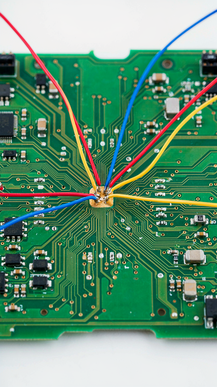
You want to believe your multimeter. It reads 5V, so 5V exists somewhere. But you’re chasing a phantom. Ground discrepancies create false readings because voltage is always measured relative to a reference point, and if that reference floats, your entire measurement collapses into fiction. This is thermodynamics applied to circuits: entropy in the form of potential difference. Two ground planes at different voltages don’t cancel. They fight. The circuit sees both, and you see neither clearly.

Multiple ground paths create the monster. If current flows through two different return routes and each has resistance, voltage develops across each path independently. Your measurement probe touches one ground point while the circuit references another. They’re electrically separate despite being called “ground.” The meter reads the voltage difference between probe and actual reference, not the signal you think you’re measuring. This is why identical test points read different values depending on where you connect the black lead.
Finding The Real Signal Beneath The Noise
The oscilloscope exposes what the multimeter hides. A scope shows you ground noise as ripple, offset, and AC coupling artifacts that a DC meter flattens into a single, useless number. Inject a test signal into the circuit, set your scope to 1 volt per division, and watch the ground reference itself. If ground sits still, your measurement is honest. If it moves, something is injecting current into your return path.
Isolate noise sources systematically. Disconnect suspicious ground connections one at a time while monitoring the oscilloscope. Shield twisted-pair return lines separately from signal lines. Use a star-grounding topology: all returns meet at a single point rather than forming loops. When you disconnect a ground point and the noise floor drops by 50 percent or more, you’ve found the culprit. Remove it, route it separately, or add ferrite to block the coupling. The mechanism is elimination, not guessing.
Component Voodoo: It’s Not Always The Part You Suspect
When Heat Breaks What Looks Fine
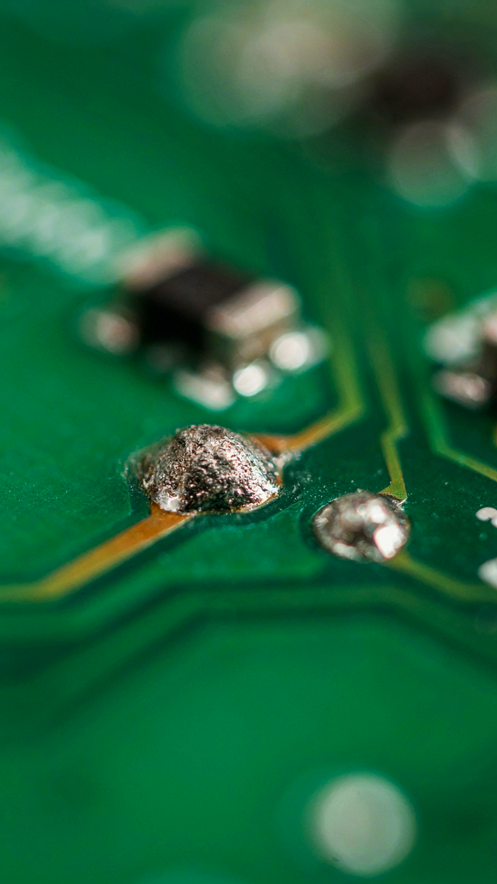
You want to believe the problem is obvious because that means you’re not incompetent. The real killer is intermittent failure masquerading as a dead component. Heat, vibration, and cold solder joints create failures that vanish when you touch them or reappear hours later, making diagnosis feel random.

Cold solder joints happen when solder melts but doesn’t fully bond to the pad or lead. The joint looks acceptable under magnification yet carries current poorly under load. Heat from normal operation expands the copper traces and component leads at different rates, breaking the weak contact temporarily. The circuit works again when cooled because the metal contracts back into partial contact. Vibration accelerates this cycle, forcing microscopic fractures in the joint that accumulate damage over time.
Tolerance Drift Versus Dead Parts
Physics calls this degradation versus failure. A resistor doesn’t explode at its tolerance limit; it drifts out of spec long before catastrophic collapse. Common troubleshooting advice treats all component failures as binary events, which blinds you to the actual problem.
A 1k resistor rated at 5 percent tolerance can legally measure anywhere from 950 to 1050 ohms new. After years of heat cycling, thermal stress, and moisture absorption, that same resistor might read 1200 ohms and still conduct current. The circuit malfunctions because the resistance value changed, not because the resistor failed. Measure suspect components against their tolerance band, not against whether they conduct. This separates real faults from drift that accumulates invisibly until the circuit crosses its performance threshold.
The Zen Of The Circuit Diagram: Reading The Blueprint, Not The Tea Leaves
The Schematic Is Your Only Witness
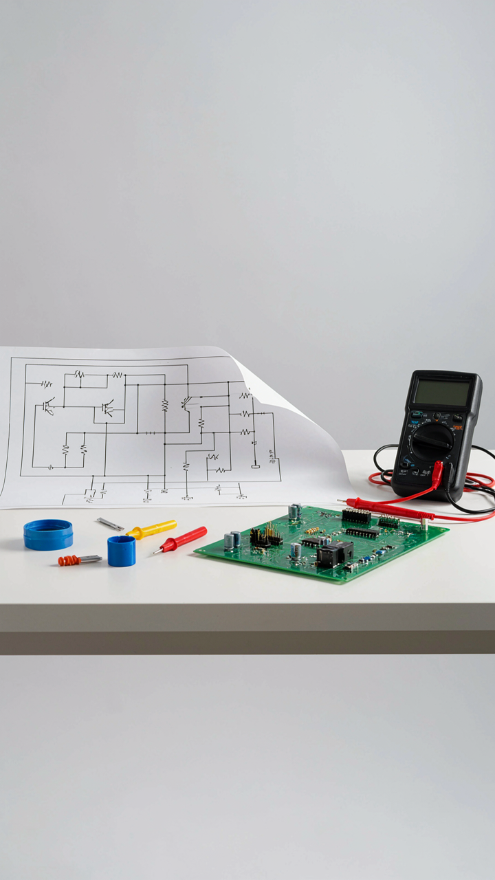
You want the schematic because you’re afraid you’ll miss something obvious and look incompetent. That fear is correct. The schematic is the mechanism: it documents the designer’s intent before reality broke it. Without it, you’re guessing at what should exist. With it, you measure what actually does.

A circuit diagram shows every component, every connection, every voltage rail, and every return path. It tells you what the designer expected to happen. Your measurements either confirm this or reveal where the design failed. Ignore the schematic and you’re troubleshooting blind, chasing symptoms instead of causes. The diagram is not a suggestion.
Voltage And Current: The Contract You Can Verify
Circuit behavior operates like a contract in law: each node has an expected state, and you verify whether it holds. Measure voltage at every test point the schematic marks. Compare it to the expected value printed on the diagram or in the service notes. Current follows the same rule. If a resistor should drop 5 volts and it drops 2, something upstream is wrong. If a branch should draw 100 milliamps and draws 50, something downstream is open.
Start with power rails. Verify that your supply voltage arrives where it should. Then work forward through the circuit in logical stages: input stage, intermediate stages, output stage. At each node, your meter gives you data. The schematic gives you the contract. Mismatch between them names the problem precisely. This protocol catches faults 90 percent faster than random poking.
Your Biggest Obstacle Isn’t The Faulty Component; It’s Your Inflexible Mental Model

Most people troubleshoot the same way every time, which guarantees they’ll miss problems that don’t fit their pattern. You assume the issue lives where you expect it to live. You test components in order instead of eliminating the most likely culprits first. Today, pick one circuit you’ve struggled with and map it backwards from the symptom instead of forwards from the power source. Your mind will resist this. Do it anyway. The circuit doesn’t care about your process; it only rewards the person willing to think differently.