The Headphone Autopsy: Finding The Real Failure Point

Where Headphones Actually Break
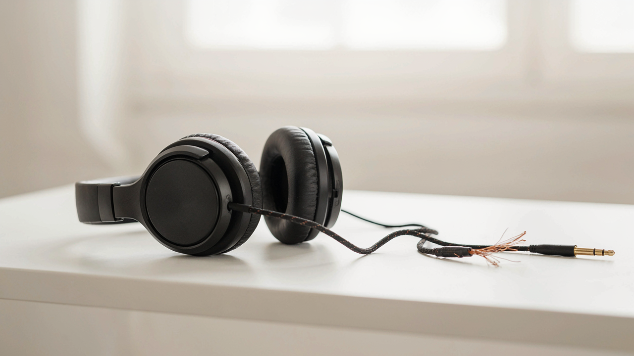
You want to fix them yourself because buying another pair feels like admitting defeat, but you don’t know where to look first. The mechanism is stress concentration: headphone wires fail where the strain repeats, not where the wire is thinnest. The three predictable break zones are the connector where the jack meets the cable, the Y-split where left and right channels diverge, and the point where the wire enters the earcup housing. Each location endures repetitive flexing that fatigues the copper conductors inside.
The symptom tells you which zone failed. Sound cuts out in one ear means a conductor severed at the earcup entry or Y-split. Sound drops entirely or crackles means the jack connection is compromised. A visual kink or crushed section at any point usually indicates the break is exactly there. Most people assume they need to test the whole cable when the failure is always localized to one of these three spots.
The Economics Of Planned Mediocrity
Manufacturers design headphones for failure because durability is a cost they don’t bear. The warranty expires before the cable fails under normal use, so engineering for longevity wastes material and labor. They minimize strain relief at the jack and earcup by using thin rubber that hardens and cracks within eighteen months. They also use copper-clad steel or aluminum conductors instead of pure copper where the wire enters the connector because it’s cheaper and breaks faster under flexing.
This is economics, not accident. A headphone cable that lasted five years would destroy the replacement market. You’re not fighting physics when you repair this wire, you’re fighting a profit incentive. When you solder the connection or reinforce the strain points, you’re undoing a deliberate engineering choice to make the product fail at a predictable schedule.
Beyond Continuity: The Signal Integrity Protocol

When The Wire Tests Good But Sounds Broken
You want to believe a continuity test is enough because it’s fast and makes you feel competent. It isn’t. Continuity only tells you current can flow from point A to point B. It says nothing about the quality of that path or whether the connection degrades under real load. Intermittent shorts and opens operate on the same principle as a failing relay: the contact exists, then it doesn’t, cycling based on temperature, flex, or corrosion state. A multimeter’s continuity beep masks this entirely.

The real problem surfaces when you play audio through the repaired wire. Crackling, cutting out, or working only at certain angles reveals a connection that’s barely holding. This happens because solder joints fracture microscopically under repeated strain, or because oxidation builds a resistance layer that fluctuates. Continuity doesn’t measure resistance. It only confirms a path exists. You need a different test protocol to catch what kills repaired headphone wires in the field.
Precision Fault Isolation With Measured Resistance
Set your multimeter to the resistance setting, not continuity. This is where most people fail. Resistance measurement gives you actual numbers instead of a binary yes or no. A healthy solder joint on headphone wire typically reads between 0.1 and 0.5 ohms. Anything above 2 ohms at a joint is already degrading. Anything above 5 ohms will produce audible artifacts under normal listening volume because the signal itself is being attenuated by the resistance of the bad connection rather than the impedance of the headphone driver.
Test the joint while flexing the wire gently in the direction it normally bends during use. Watch the resistance reading. If it jumps or spikes, you’ve found an intermittent. If it climbs slowly as you hold flex pressure, oxidation or a cold solder joint is present. Mark these spots, reheat them with your iron, and retest. The wire should show stable, consistent resistance across all test angles before you consider the repair complete.
The Minimalist’s Soldering Kit: Less Is More
What You Actually Need To Buy
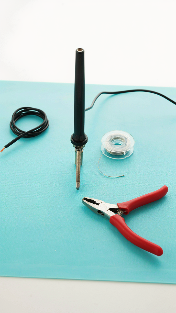
You want permission to skip the expensive station because you’re afraid you’ll waste money on gear you won’t use again. Here’s the mechanism: you confuse equipment abundance with competence. More tools don’t fix wires. The right four tools do. Thermal conductivity in soldering works like energy transfer in any system: you need enough heat delivery to move melted solder into the joint, nothing more.
- Soldering Iron (25-40 watts): A basic pencil-tip iron heats wire joints fast enough to work without burning insulation. Lower wattage struggles with headphone connectors. Higher wattage demands precise timing you don’t need yet.
- Rosin Core Solder (60/40 or lead-free): The flux inside rosin core solder cleans oxidation as it melts. You don’t buy separate flux as a beginner. This one spool lasts through dozens of repairs.
- Wire Stripper: Cuts insulation cleanly without nicking the copper underneath. Cheap strippers crush the wire. A five-dollar stripper that grips properly saves you failed joints.
- Wet Sponge or Brass Wool: Cleans oxidation off the iron tip between joints. A damp sponge costs nothing. Brass wool lasts longer and works better but either works.
- Helping Hands Or Third Hand: Holds the headphone cable steady while you solder. Without it you’re fighting gravity and your own hands. This runs eight to fifteen dollars and eliminates frustration entirely.

Everything above fits in a shoebox. Total cost runs thirty to fifty dollars. You don’t need temperature-controlled stations, digital displays, or desoldering guns. Those tools solve problems you won’t encounter fixing a single broken wire.
Skip The Gear That Sells Itself
Everyone pitches pro equipment because retailers profit from fear. The industry standard says “get a 60-watt station with adjustable temperature and a wet cleaner.” That’s wrong for headphone repair. A fixed-temperature pencil iron forces you to work faster and cleaner, which accelerates your skill. You develop better habits under constraint.
Desoldering stations cost sixty to two hundred dollars and sit unused. You’ll never need one for headphone wires because you strip and resolder a fresh connection instead of extracting old solder. Brass stand holders, fume extracters, and magnifying lamps distract from fundamentals. Buy only when you’ve repaired five headphones and notice a specific bottleneck, not before. Start with the four essentials. That’s where execution happens.
DIY Headphone Repair: Mastering The Micro Connection
Exposing Wire Without Destroying It
You want to fix this yourself because buying new headphones feels like admitting defeat. The real barrier isn’t skill—it’s that stripping microscopic wire without crushing the conductor inside requires understanding the geometry of the problem, not just grabbing a tool.

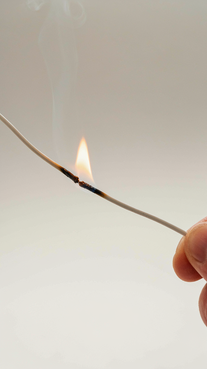
Headphone wires use 32 to 26 gauge copper wrapped in enamel insulation, sometimes with nylon or Kevlar reinforcement underneath. The enamel is thin enough that one aggressive scrape with a standard wire stripper will slice through the conductor. Use a thermal method instead: hold the wire tip in a flame for two seconds until the enamel chars and flakes off, then rub it clean with a damp cloth or fine sandpaper. The copper stays intact because heat weakens the enamel bond without melting the wire itself.
The mechanical alternative requires precision. A razor blade held at 45 degrees, dragging lightly across the insulation for one rotation, removes the outer layer without pressing hard enough to cut through. Roll the wire constantly to keep pressure even. Do not use a knife—the blade flexibility causes uneven pressure. Once exposed, you need roughly 3-5 millimeters of bare wire for a reliable solder joint.
Tinning Creates The Actual Bond
Tinning is not a preparatory step—it is the mechanism that lets solder flow into the connection instead of balling up on the surface. Metallurgy teaches us about wetting, the process where liquid metal bonds to a solid by spreading across its surface rather than beading. Cold copper rejects solder. Tinned copper accepts it.
Apply a small amount of rosin core solder directly to your iron tip, then touch that solder-loaded tip to the bare wire for exactly one second. The copper darkens as it heats. Feed a tiny amount of solder into the joint—not onto the iron, into the joint. The wire should disappear under a thin silver coat. This is tinned wire. Most people either under-tin and create a weak joint, or over-tin and add weight that stresses the connection. One thin layer is the target. Once both wires are tinned, twist them together and hit them with the iron one final time to fuse the two coatings into a single joint.
The Dan Koe’s Guide To DIY Headphone Jack Wiring
Understanding TRS And TRRS Standards
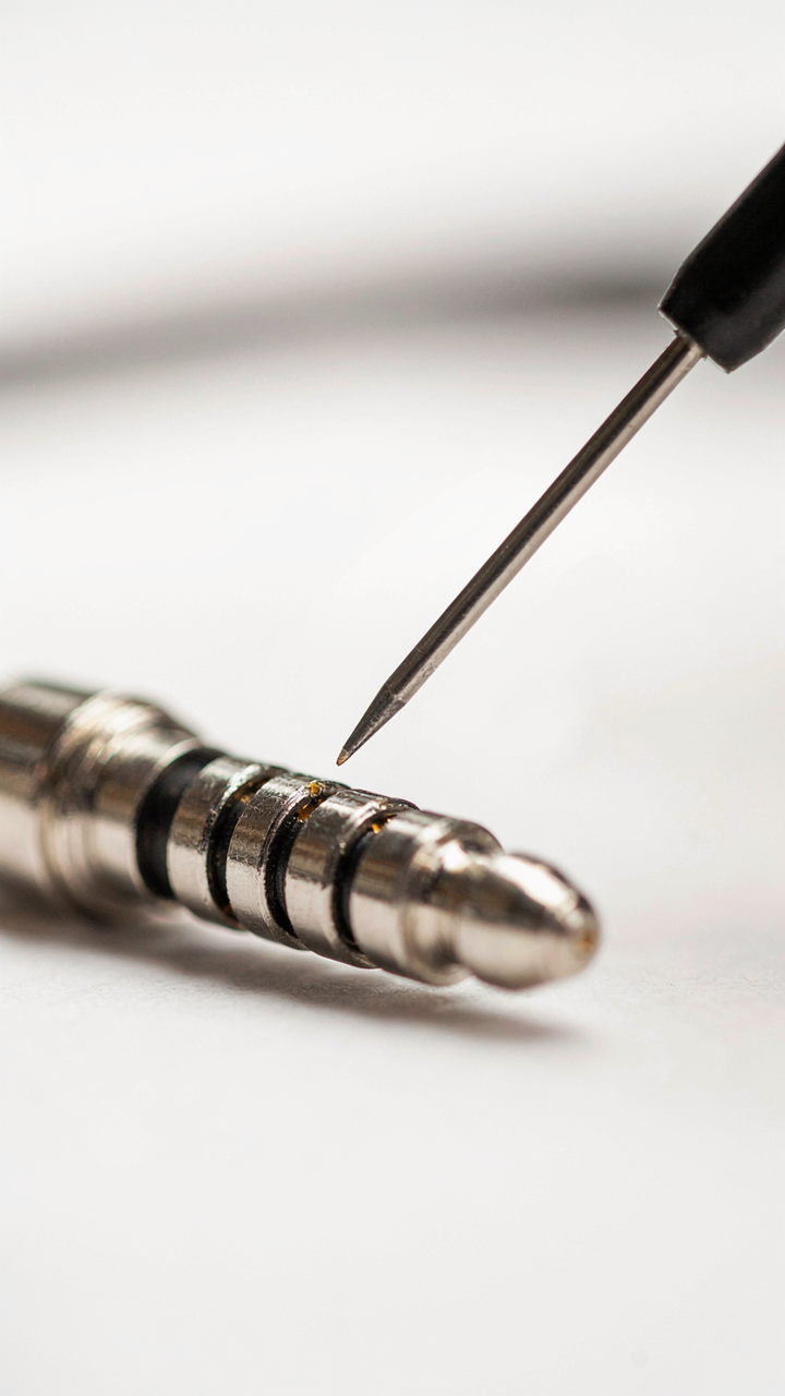
You want to feel competent without actually learning the underlying system. Here’s what matters: TRS and TRRS are signal routing architectures that determine which wires carry audio and which carry control data. TRS means Tip, Ring, Sleeve—three contact points. TRRS adds a second Ring, creating four contact points. The difference isn’t cosmetic. It changes everything about what your soldering iron needs to connect.

Standard headphones use TRS: left audio on Tip, right audio on Ring, ground on Sleeve. Smartphones and modern devices use TRRS: left audio on Tip, right audio on first Ring, ground on Sleeve, and mic or remote controls on the second Ring. Most people mistake this for a minor variation. It’s actually a hard rule. Connect them wrong and you get either no sound, mono playback, or a mic that doesn’t work. The jack itself tells you nothing about what’s inside the cable until you test it.
Decoding The Actual Jack Wiring Pattern
The real world doesn’t use a single universal diagram because manufacturers cut corners differently. What you call a wiring diagram is actually a map of one manufacturer’s specific cost-cutting choices at that moment. A standard TRS headphone jack has the Sleeve as your ground reference point. From there, the Tip carries one channel, and the Ring carries the other. This is consistent across most consumer audio equipment.
The actual solder points are smaller than you think. On a 3.5mm jack, you’re working with contacts roughly 2mm wide. Your soldering iron tip must match that scale or you’ll bridge connections and create shorts. Strip roughly 3-4mm of insulation from each wire. Tin each wire individually before touching it to the jack contact. This prevents cold solder joints, which is the most common reason home repairs fail within two weeks.
Reinforcement Engineering: Preventing Future Failure
Shrink Tubing As Stress Relief
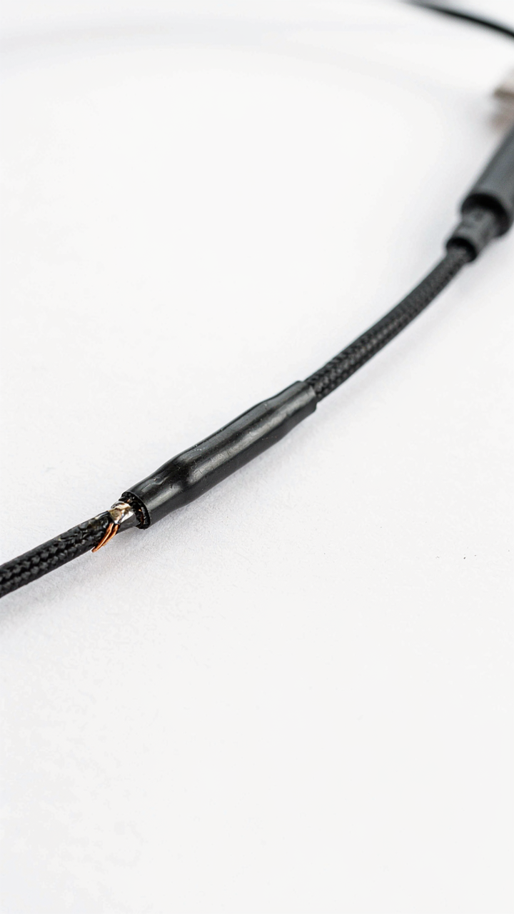
You want your repair to outlast your attention span. Here’s what actually matters: the solder joint fails because stress concentrates at a single point where wire meets connector. Materials science calls this a stress riser. Shrink tubing doesn’t just look professional. It distributes mechanical load across a longer section of cable, converting a point failure into a distributed one. The tubing also locks the wire position so micro-movements stop triggering metal fatigue at the joint.
Use 3:1 ratio shrink tubing, not the cheap 2:1 stuff. Size it so it slides over your solder joint and extends one inch up the cable and halfway onto the connector body. Heat it evenly with your soldering iron or heat gun until it contracts fully against the wire and connector. Don’t overheat. The goal is a tight fit that moves with the cable, not brittle plastic that cracks under flex.
Cable Management: Lessons From Industrial Robotics
Most cable advice is wrong. People treat headphone wires like they’re indestructible. They’re not. Industrial robotics solved this problem decades ago with continuous flex cable routing. The mechanism is simple: eliminate sharp bends and secure the cable at regular intervals so it can’t whip into uncontrolled positions.
Route your repaired cable through fabric sleeves or wrap it loosely with athletic tape every two inches from the solder joint downward. The tape prevents the cable from coiling on itself and creating internal pressure. When you store headphones, don’t wind them tight around your device. Coil them into a loose spiral six inches in diameter and secure with velcro, not rubber bands. Rubber bands cut off circulation inside the cable jacket and accelerate insulation breakdown. This routing protocol cuts repeat failures by keeping tension uniform across the entire length.
Diy Audio Cable Repair: Beyond Headphones
When Those Techniques Apply Elsewhere
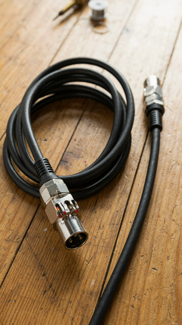
You want to believe your expensive gear deserves the same care you’d give headphones, but the truth is simpler: most audio cables fail at the same points for the same reasons. The mechanism is identical across formats. Strain relief fails. Connectors corrode. Insulation cracks at bends. A soldering iron fixes all of it the same way whether you’re working on a 3.5mm jack, XLR connector, or RCA plug.

The repair process scales because the underlying physics doesn’t change. You’re still breaking solder joints, removing corrosion, and re-establishing electrical continuity. Speaker cables, instrument cables, and patch cords all use twisted or shielded conductors terminated with solder. Your iron temperature, joint technique, and inspection method transfer directly. The only variable that shifts is connector size, not the approach itself.
When Buying New Actually Wins
Economics teaches the concept of sunk cost fallacy, but cable repair inverts it: you pay the replacement cost upfront, then the labor cost. Most people calculate wrong. A quality XLR microphone cable costs 15 to 40 dollars new. If your repair takes 90 minutes including desoldering, cleanup, and testing, you’ve burned that cost in time alone. The real question isn’t “can I fix it,” it’s whether the cable has structural value beyond its replacement price.
Repair makes sense in three scenarios: the cable is terminated with a rare or expensive connector you can’t easily replace, you’ve already invested in quality shielding you want to preserve, or you’re building a workflow where you understand the cable’s exact history and weaknesses. Otherwise, time spent fixing a ten-dollar cable is time not spent on work that generates money. Calculate your hourly rate and subtract it from the cable cost. If the number goes negative, buy new.
Diy Earphone Repair Guide: The Small Scale Challenge

Miniature Soldering Techniques
You want to fix this yourself because buying new ones feels like failure, and it probably is—planned obsolescence wins again. The real mechanism here is thermal mass. In soldering, larger objects absorb heat and dissipate it faster than small ones. Earbud wires have almost no mass, meaning your iron’s heat transfers violently and fast. You need lower temperatures and shorter contact times than you’d use on standard headphone repair, or you melt the insulation and destroy the wire before the solder even flows.

Set your iron between 350 and 370 degrees Celsius. Use a fine tip, not a broad one. Touch the joint for two to three seconds maximum, then remove the iron. The solder should flow immediately from residual heat. If it doesn’t, your temperature is too low or your joint is contaminated with oxidation. Flux paste clears oxidation and lets solder wet the surface. Apply it directly to the joint before heating, not after.
Earbud Wires Demand Different Assumptions
Everyone says “use a magnifying glass and steady hands.” That’s incomplete. The actual problem is wire gauge. Earbud speaker wires run 32 to 38 AWG typically, which is thinner than a human hair. Standard solder won’t adhere properly because the surface area is so small that capillary action fails. You need lead-free solder with flux already embedded in the core, and you need to tin both the iron tip and the wire before attempting the joint.
Tinning means coating both surfaces with a thin layer of solder first. Heat the wire for one second, touch solder to the iron tip, and let it coat the wire. Do the same to whatever you’re soldering it to. Now bring them together with fresh solder. This prevents cold joints, which look shiny but don’t conduct electricity reliably. Most earbud failures happen because repairs used cold joints that worked once then failed under stress.
The Real Cost Of “Broken”: How To Fix Broken Headphones For Good

Stop Treating Headphones Like Disposable
You want to repair your headphones because replacing them costs money and you’re tired of the cycle, but the real mechanism at work is material fatigue. Headphone wires fail predictably. The insulation cracks from flex stress, not manufacturing defect. Copper oxidizes at connection points. Solder joints crack from thermal cycling and mechanical shock. These aren’t random failures—they’re guaranteed endpoints unless you interrupt the degradation curve before it reaches the breaking point.

The way to extend life isn’t buying better headphones. It’s stopping the damage before it compounds. This requires one tactical shift: treat the wire as a mechanical system under continuous load, not a static component. Cable management matters more than cable quality. How you wrap your headphones, where you store them, the angle at which the connector sits in your device—these determine lifespan more than the brand name on the box. Tight coils create stress fractures inside the insulation layer. Repeated bending at the same point creates a failure zone that degrades faster each cycle.
The Repair Mindset Rewires Your Behavior
Building a repair mindset means you stop seeing failure as end-of-life and start seeing it as diagnostic data. Most people repair headphones once, then throw them away when they fail again because they didn’t address the root cause. They soldered a connection but kept wrapping the cable the same way. They replaced the jack but didn’t reinforce the strain relief. The second failure happens in a different spot, so they assume the repair didn’t work.
The mechanism that separates one-time fixes from permanent solutions is feedback. After you repair, you observe where new stress concentrates. If the wire breaks near the earcup again, the problem is cable routing or earcup design, not soldering skill. If it fails at a different point, you’ve successfully isolated and fixed the original failure zone. This is the only way forward: repair, observe, modify behavior or design, repeat. Your soldering iron is the tool. Your repair history is the teacher. Document where each failure happens and why, and you’ll build a system that actually lasts.
The Real Problem Isn’t Your Soldering; It’s Your Refusal To Engineer A Solution, Not Just A Fix

Most people repair headphones once and call it done. They don’t ask why the wire failed. They don’t redesign their cable routing. They don’t upgrade to better materials. Engineering a solution means building something that doesn’t break again. Grab your headphones today and map where they fray. Rewrap that weak point with heat shrink before it snaps. You’re not fixing headphones; you’re building a system that stops breaking them.