
The Myth Of Always Replace All Capacitors In Vintage Tube Radio Circuits
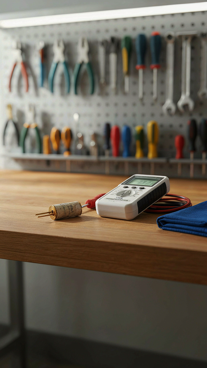
Original Design Held Up Better Than You Think
You want permission to leave things alone because replacing capacitors feels risky and expensive. Here’s the mechanism: tube radio designers built in margin. They ran capacitors at 50 to 70 percent of rated voltage, not 90 percent. A paper capacitor rated for 600 volts in a 1950s radio chassis typically saw 300 to 400 volts actual stress. That’s engineering restraint, not accident.
The obsessive “recap everything” directive ignores material reality. Capacitors from the 1940s through 1960s that were never subjected to heat damage, moisture intrusion, or power surges often hold their capacitance within acceptable tolerance today. Military and professional broadcast equipment from the same era still operates with original capacitors because the design margin absorbs decades of degradation. Cosmetic failure (a dried-out case) does not equal electrical failure.
Spotting Real Failures Versus Aging Cosmetics
The common advice is incomplete: technicians tell you to replace based on age alone. That’s lazy diagnosis. Electrolytic capacitors fail in specific, observable ways. When the rubber seal at the base cracks and leaks electrolyte, the capacitor is done. When you measure capacitance and it reads 15 percent below spec or higher than spec, it’s failed. When DC leakage current tests show excessive bypass, replace it.
Paper and film capacitors rarely fail catastrophically after sixty years of stable storage. They dry out and lose slight capacitance, but a 10-microfarad capacitor reading 8.9 microfarads is still functional in most coupling and blocking roles. Test first. Use a capacitance meter and ESR meter. Document actual values against schematic specs. Replace only what measures outside tolerance or shows physical damage like bulging or leakage. This is the protocol: measure, document, then decide.
Why Old Radios Aren’t Time Bombs: The True Failure Modes Of Vintage Capacitors
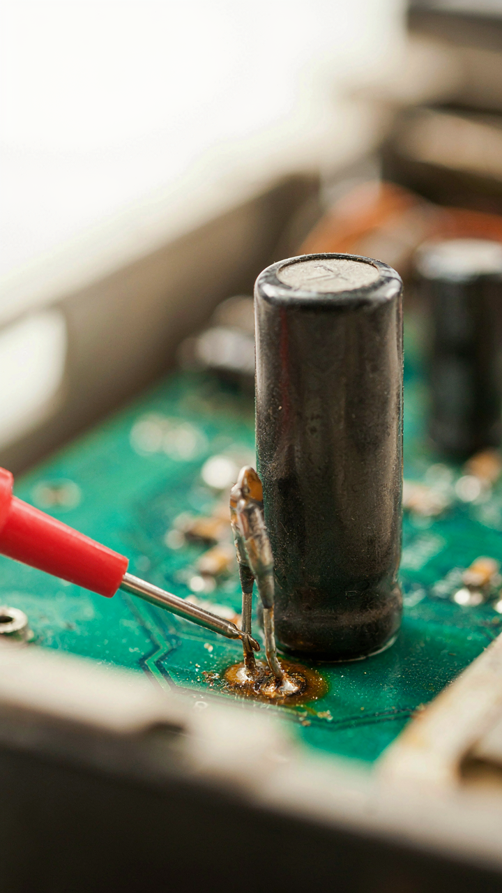
When Dielectric Breaks Down
You want to know if your radio will explode because you’re afraid you’ll waste money fixing something that wasn’t actually broken. The physics here is straightforward: dielectric breakdown happens when voltage exceeds the material’s insulation threshold, forcing current through what should be an insulator. In vintage radio capacitors, the dielectric—paper impregnated with wax or oil, or ceramic—degrades chemically over decades. Heat accelerates this. Humidity penetrates paper dielectrics and reduces their voltage rating. The capacitor doesn’t fail catastrophically. It leaks.

Leakage current draws power continuously, warming the component further and degrading it faster. Electrolytic capacitors from the 1940s through 1960s leaked most aggressively because aluminum oxide dielectrics break down in hostile environments. Paper and ceramic types leak slower but still degrade. The mechanism is predictable: measure voltage across the suspect capacitor with the radio powered off for five minutes. If you read voltage present on a coupling capacitor that should be DC-blocking, leakage is active. That’s your signal to replace it.
Predicting When Age Turns To Failure
Most advice says “replace everything over 50 years old.” That’s lazy. Capacitor failure depends on storage temperature, humidity exposure, and applied voltage stress—not calendar years alone. A paper capacitor stored in a dry basement behaves differently than one in an attic that cycled through summer heat. Electrolytic capacitors fail first because their electrolyte evaporates. Ceramic disc capacitors from the 1950s often outlast the chassis around them.
Test before you replace. Use a capacitance meter on suspected components with the radio unplugged and capacitors discharged. Electrolytic capacitors that measure significantly low on value or show high resistance when you first apply the meter are candidates for replacement. Coupling and bypass capacitors showing 20 to 50 percent value drift warrant attention. Power supply filter capacitors that measure more than 30 percent below spec are creating voltage ripple that stresses tubes and transformers. Replace that tier first, then return to the radio after a week of use to see if new faults emerge.
The Preservation Vs. Practicality Protocol For Retro Radio Restoration

Original Components Tell A Story You Cannot Fake
You want to keep the radio original because you think it proves something about your taste or knowledge. Here’s the mechanism: vintage radio capacitors fail predictably because the dielectric materials degrade over decades. Electrolytic caps dry out. Paper and wax caps absorb moisture. This isn’t reversible. Original components in a 1940s radio are statistically certain to be electrically unstable or dangerous after 80 years.

Authenticity has a real cost that most restorers won’t admit. A radio with failed original capacitors draws excessive current, generates heat in the transformer, and risks fire or electrical shock. The question isn’t whether to replace them. The question is whether you value the object more than safe operation. Those are incompatible goals in most cases. Measure the actual voltage and ESR of original caps before deciding they’re fine.
Repair First, Replace Second
Start by identifying which capacitors are critical to safety versus cosmetic to the circuit. The power supply capacitors (main filter caps and any on the primary side) are non-negotiable replacements. They control voltage stability and current limiting. Coupling caps and tone control caps can sometimes stay original if they measure within acceptable ESR ranges and voltage ratings haven’t drifted.
- Power Supply Capacitors: Replace always. These prevent voltage spikes that damage tubes and create fire risk in the transformer. No exception.
- Electrolytic Coupling Caps: Test ESR first. If ESR exceeds 10 ohms or capacitance has dropped more than 20%, replace them. Original values are secondary to functionality.
- Paper and Wax Capacitors: Check dielectric resistance with a megohm meter. If leakage current exceeds 100 microamps at rated voltage, replace. Otherwise, they may hold if sealed from moisture.
- Cathode Bypass Caps: These affect tube bias and gain. Failing originals cause distortion and tube stress. Replace if ESR is above 5 ohms or if capacitance is unmeasurable.
- Tone Control and High Frequency Caps: Lowest priority for replacement. These rarely fail catastrophically. Replace only if the circuit exhibits dead channels or extreme noise.
A practical restoration protocol means you replace failed components with correct values and voltage ratings but use modern film or electrolytic caps designed for audio frequencies. Your radio functions safely and sounds correct. The trade is that it’s no longer 100% original. That trade is worth making.
The Decoupling Delusion: Why Most Capacitor Upgrades Are Overkill
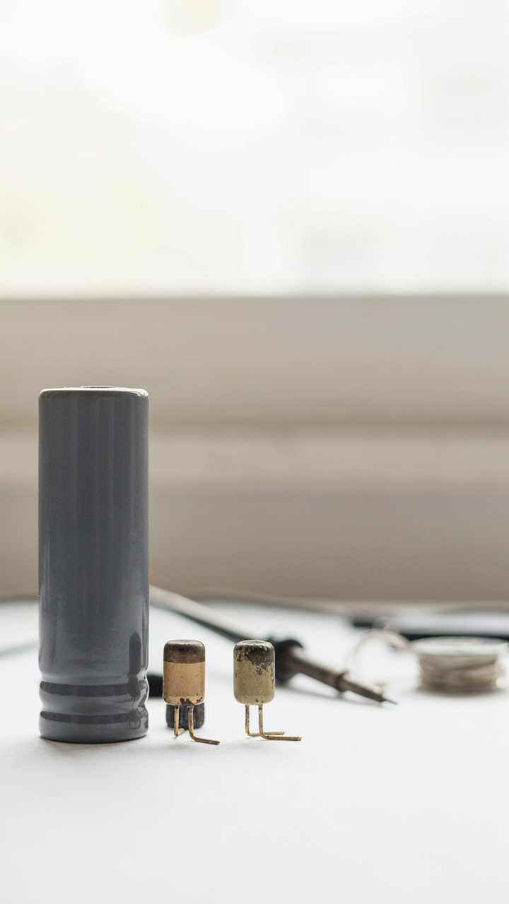
The Ripple Myth Nobody Questions
You want to believe the radio sounds better because you spent money on it. Here’s the mechanism: vintage radio designers didn’t chase ripple reduction like modern audio engineers do. They built circuits that worked within specific voltage tolerances. A 1950s AM receiver didn’t need film capacitors with 0.1% tolerance or ceramic replacements rated for half the ripple voltage of the original. The radio powered on and stayed stable. That was the entire requirement.

Modern capacitor sellers pitch ripple reduction and “cleaner audio” because those concepts sell. They borrow language from power supply engineering where ripple matters in precision instruments. But a vintage radio isn’t a precision instrument. It’s a device that runs on AC mains converted through a simple rectifier. Adding a capacitor with lower ESR or higher voltage rating doesn’t fix what wasn’t broken in the first place. You’re replacing something functional with something expensive for a benefit you can’t measure and don’t need.
Circuit Stability Over Audio Theater
The original design worked with the capacitors it shipped with. Your job is to restore that stability, not rebuild it to modern specifications. A vintage radio’s power supply capacitor had one job: smooth enough ripple to prevent hum and oscillation in the audio stages. A tube rectifier into a 40-microfarad electrolytic at 450 volts did exactly that for decades. Upgrading to a 100-microfarad 600-volt capacitor changes the circuit’s electrical behavior in ways the designer never accounted for.
The mechanism is straightforward: capacitance value and voltage rating affect startup transients, charging curves, and how the power supply responds to load changes. A larger capacitor charges slower initially, which can affect tube warm-up sequencing. A higher voltage rating changes the physical size and internal construction, shifting where the real impedance sits across the frequency range. You’re not improving the circuit. You’re making it different from what it was engineered to be. Replace with exact original specifications or a direct electrical equivalent, verify the radio powers on without arcing or component strain, then leave it alone.
The “Systemic Vulnerability” Framework: Borrowing From Cybersecurity For Vintage Electronics
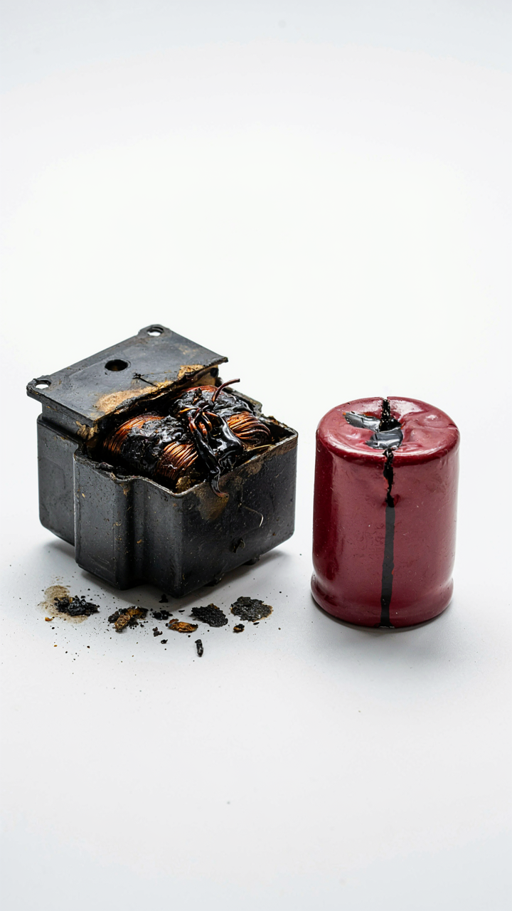
Where Your Radio Fails When One Part Dies
You want to feel in control of your radio’s lifespan. The real mechanism you’re missing is this: vintage radios fail catastrophically because one failed capacitor takes the whole power supply with it. Cybersecurity calls this a single point of failure. In a radio, that’s typically the large electrolytic filter capacitor sitting between the rectifier and the first stage of voltage regulation. When that capacitor dries out or shorts, it stops blocking DC ripple, floods downstream circuits with AC noise, and often burns out transformers or output tubes before you even realize something’s wrong.

The vulnerability isn’t random. The filter capacitor sits at the convergence of highest voltage, highest current draw, and maximum heat stress. It ages faster than surrounding components because electrolytic capacitors lose capacitance and gain equivalent series resistance over decades. One failed component doesn’t just stop functioning. It propagates damage through the entire power architecture because nothing downstream expects raw, unfiltered DC to arrive. That’s the mechanism nobody names plainly: serial dependency disguised as parallel redundancy.
Layered Defense Against Cascade Failure
The conventional advice says “replace all the capacitors.” That’s incomplete. Real protection means building defense depth so no single failed component propagates damage down the circuit chain. Think of it like network security architecture: you need barriers at multiple stages, not faith in one strong gate. In radios, this means installing isolation at the power input, installing fuses that trip before components burn, and verifying ground paths that actually dissipate fault current instead of letting it loop through signal circuits.
Start by mapping where voltage enters the radio and where it exits to ground. Fuses go in the primary AC line before the transformer, stopping shorts upstream. The filter capacitor gets replaced with a modern equivalent rated for higher voltage than the original specification, adding margin that absorbs aging stress. Secondary fuses protect individual voltage rails feeding the IF strip, audio output, and tube heaters. Ground connections must run directly to a central point, not daisy-chain through multiple components. This isn’t defensive overkill. It’s the standard topology that keeps one failed part from cascading into five.
Beyond ESR: The Unspoken Metrics Of Vintage Capacitor Performance

Insulation Resistance And Dielectric Absorption
You want to believe ESR is the full story because it’s measurable and lets you feel in control. It isn’t. Borrowing from materials science, a capacitor’s dielectric is like a loaded spring: it stores charge beyond what voltage accounts for. Insulation resistance measures how much current leaks through the dielectric itself over time. Old capacitors lose insulation resistance first, sometimes decades before ESR climbs enough to matter. A 50-year-old paper-in-oil capacitor might show acceptable ESR yet pull microamps continuously—draining batteries, generating heat, altering bias points in RF circuits.
Dielectric absorption happens when a capacitor discharges and still releases trapped charge hours later. This creates phantom voltages in sensitive circuits. Vintage mica and paper capacitors exhibit this behavior far more than modern film types. When you power down a radio and the tubes still glow faintly from residual charge, dielectric absorption is often the culprit. Replace the capacitor and that ghost voltage vanishes. This metric doesn’t show up on an ESR meter—you only catch it by measuring voltage decay over minutes after full discharge.
How These Metrics Reshape Circuit Behavior
The common advice says replace capacitors when they fail. Wrong. A failing capacitor doesn’t fail cleanly—it drifts the circuit into a state where nothing works as designed. High insulation leakage throws off biasing networks, especially in push-pull output stages where balance matters. Dielectric absorption causes oscillation in feedback loops and creates unpredictable frequency drift in oscillator stages. High-impedance circuits like grid-leak biasing become sensitive to these effects first. A capacitor with 1 megaohm insulation resistance instead of 10 gigaohms changes tube current draw, output impedance, and audio character noticeably.
Sound quality in vintage radios depends on capacitors holding their charge without leaking or releasing ghost voltage during signal transitions. Capacitors that absorb and re-release charge create phase shift in the audio band, dulling transients and muddying midrange. The replacement protocol is this: measure insulation resistance on suspected caps using a megohmmeter at the radio’s operating voltage, not just at 500V. If insulation resistance falls below 100 megohms, replace it. If dielectric absorption matters for your application, choose film capacitors over paper as replacements—they exhibit almost no absorption.
The Capacitor Contradiction: New Isn’t Always Better For Vacuum Tube Tone
When Specs Betray The Original Design
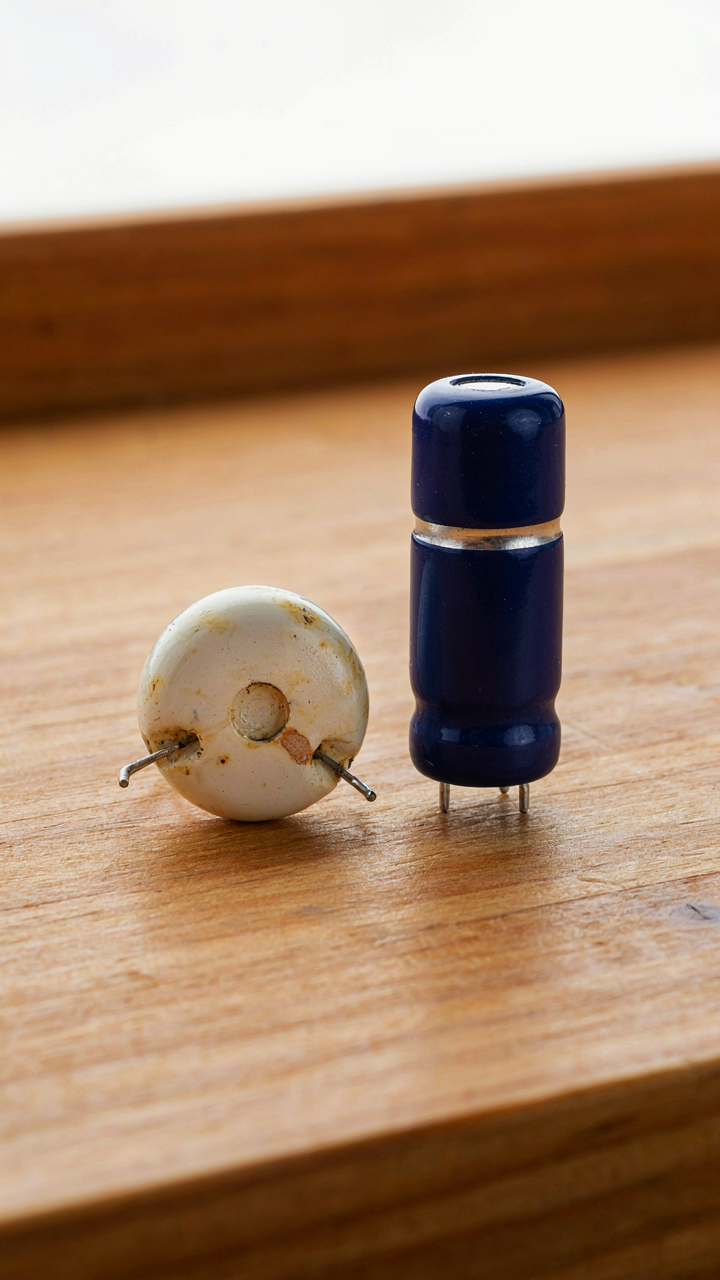
You want to believe upgrading to modern capacitors fixes everything. They’re rated higher, tighter tolerances, better isolation. But you’re really asking for permission to ignore what the radio’s designer actually chose, and that’s where the contradiction lives. The original designer didn’t pick capacitor values randomly. They selected specific types—paper-in-oil, ceramic disc, mica—because those materials shaped the circuit’s impedance curve at radio frequencies.

Modern film and electrolytic capacitors have different dielectric properties. A film capacitor’s capacitance stays flat across the audio and RF spectrum, while vintage paper capacitors exhibited gradual capacitance shift with frequency. The radio’s tone stack, coupling circuits, and filter stages were tuned to that behavior. Swap in a modern polypropylene cap and you’ve changed the circuit’s frequency response, not improved it. The engineer built the radio to work with capacitor drift. You’re erasing that by design.
The Frequency Response You Didn’t Know Was Built In
Use circuit analysis here: a capacitor isn’t a fixed value but a frequency-dependent component. In radio work, reactance changes with frequency. A vintage paper capacitor at 10 kHz behaves differently than at 100 kHz due to dielectric absorption and loss characteristics. The radio’s audio tone was partly a function of this. Modern caps eliminate that variation, which sounds cleaner on a meter but thinner through a speaker.
This doesn’t mean original capacitors are superior. It means they’re different, and the radio was voiced around their specific limitations. If you replace them with specs that read identical on paper but different in the frequency domain, you’ve detuned the set. Original tone lives in those imperfections. Restoring it means matching capacitor type and material when possible, not just ohm values and voltage ratings.
The “Minimal Intervention” Method For Safer Power On In Old Radios
Which Capacitors Actually Need Replacement
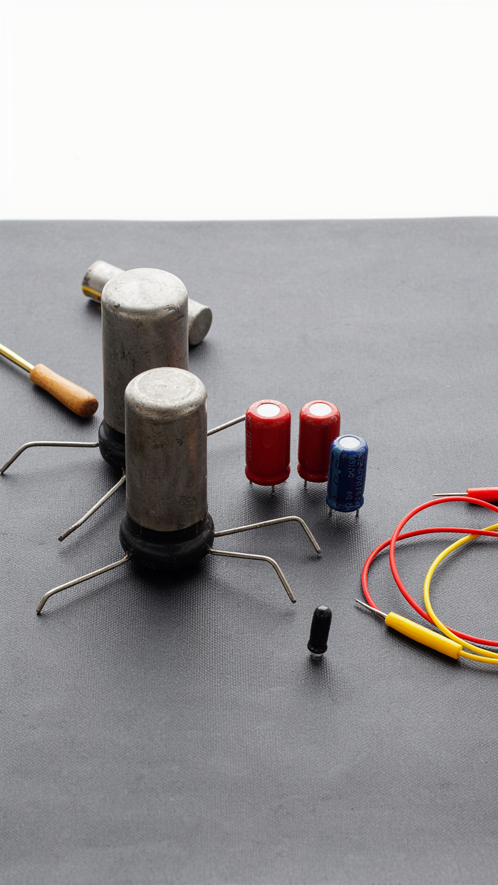
You want to power on your vintage radio without it catching fire, and you’re hoping someone tells you exactly which parts to swap. Here’s the mechanism: electrolytic capacitors degrade over decades because their electrolyte dries out. In radio design, think of capacitor health like military supply lines—the weakest link determines whether the whole operation fails safely or catastrophically. Power supply filter capacitors fail first and hardest because they sit closest to the transformer and handle peak voltage stress continuously.

The common advice to “recap everything” wastes time and money. Replace only the electrolytics in the power supply first: the main filter caps across the transformer secondary, any smoothing caps tied to the B+ rail, and any electrolytics in the output stage. Bypass caps and small electrolytics in audio coupling circuits can wait. The power supply caps are your fire risk. Everything else is secondary.
Initial Power Up And Verification Sequence
This is not guesswork territory. You follow a protocol before applying full line voltage.
- Isolation transformer setup: Run the radio through a variac (variable autotransformer) stepped up slowly from zero, not directly from wall power. This catches a shorted filter cap before it melts.
- Voltage check at B+ rail: Measure DC voltage at the positive supply rail before and after filter capacitors settle. If voltage climbs abnormally fast or spikes, a cap has failed internally.
- Load resistor test: Connect a 100-watt resistor across the speaker terminals. This draws current and stresses the output stage without playing audio through a speaker yet.
- Temperature observation: Place your hand near the output transformer and power transformer after five minutes at half voltage. If either is too hot to touch, shut down immediately.
- Standby listening: Before advancing the variac, listen for transformer hum or buzzing. A loud hum means a capacitor is shorted or severely degraded.
Once these checks pass at 50 percent line voltage, advance the variac to full voltage in small increments. Monitor B+ rail voltage with a meter while you advance. If voltage stabilizes and stays stable for ten minutes with the load resistor drawing current, the power supply is holding. Only then do you connect a speaker and run a signal through the audio stages.
Assemblage Of Knowledge: Integrating New Parts Without Destroying History

Document Everything Before You Touch Anything
You want people to know you did this right, not just that you did it. The real mechanism here is reversibility—treating the radio like a legal document where every edit gets recorded. Take photographs of the original capacitor location, orientation, and part number before removal. Note the exact voltage and capacitance rating. Record the date and the new component specifications. This creates a chain of custody that protects both the radio’s integrity and your credibility if future work is needed.

Write down the original schematic reference designations and cross-reference them to the physical board layout. If the radio uses paper capacitors wrapped in cloth, photograph the color bands and any factory markings. Store these images with the radio’s service record. The owner or next restorer will inherit a complete picture of what changed and why. This prevents someone from guessing six years from now about what you actually installed, and it prevents you from forgetting your own decisions.
Strategic Placement Preserves Function And Access
Future serviceability wins when you treat the radio like infrastructure, not a museum piece. The real constraint is thermal stress and vibration tolerance—use engineering logic, not nostalgia. Mount replacement capacitors where the original ones sat if the footprint allows modern components. If you must place them elsewhere on the chassis, secure them to the frame itself, never floating on wires. Vibration from speaker movement or transformers will work loose connections that aren’t physically supported.
Keep replacement capacitors away from heat sources like power transformers and tube sockets. Modern film capacitors tolerate temperature shifts better than older electrolytics, but proximity to tubes shortens lifespan and makes future replacement harder. Label each new component with a small tag stating installation date, part number, and voltage rating. The next tech who opens this radio needs to see immediately which capacitors are original and which are restored. This eliminates guesswork and prevents accidental damage during later work.
The Real Obstacle Isn’t The Component; It’s Your Unexamined Assumptions About What Makes A Circuit Truly Safe And Reliable
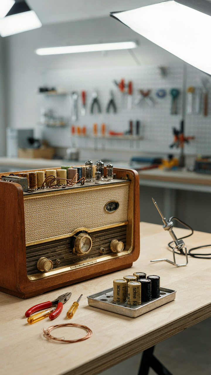
Most people treat vintage radio capacitors like a problem to outsource. They don’t. You already have the knowledge to identify which ones fail and why. Stop waiting for permission. Pull that radio apart today, test one capacitor with a multimeter, and watch what happens. The shift from passive observer to active fixer changes everything about how you approach equipment reliability. You don’t need a degree in electronics to keep something alive; you need curiosity and willingness to get your hands dirty. Safe circuits aren’t built by avoiding old parts, they’re built by people who actually know what they’re replacing and why.



