
The Unspoken Dangers: Why Your “Basic” Knowledge Is A Liability

Capacitors Hold Their Charge Like Ammunition In A Loaded Magazine
You’re reading this section because you want to feel safe without actually changing your behavior. Here’s the mechanism: capacitors in tube radios store electrical energy after power is cut. They don’t discharge on their own. A radio unplugged for weeks still holds lethal voltage across its filter caps and high voltage supply nodes. This isn’t theory. This is physics operating whether you acknowledge it or not.
The moment you touch a live capacitor terminal, that stored energy dumps through your body in milliseconds. Your nervous system runs on electrical signals. Introduce 300 volts and the signals stop. The capacitor doesn’t care that you “just wanted a quick look.” Discharging every high voltage capacitor to ground before touching anything inside the chassis is non-negotiable, not optional. Use an insulated screwdriver across the terminals, or a dedicated capacitor discharge tool. No exceptions.
Lethal Voltages Demand Respect Through Protocol, Not Intuition
Military engineers call this “fail-safe design” — building systems where the default state after power loss is safe. Tube radio designers did the opposite. They built for cost. A radio’s high voltage supply typically runs 300 to 500 volts DC. Your heart stops reliably at 100 volts across the chest. Intuition tells you a radio sitting silent for a month is dead. Intuition is wrong.
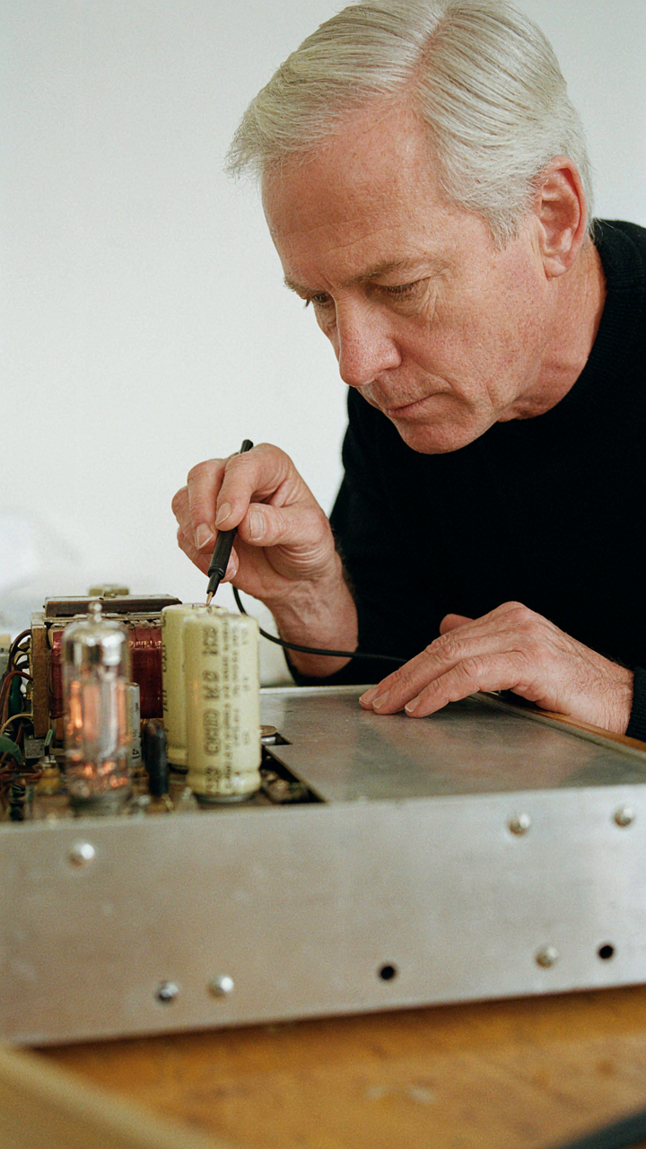
Respect for lethal voltage means treating the chassis as hot until proven otherwise. Touch nothing inside without a multimeter confirming zero volts at every major node. Work one-handed when testing, keeping your other hand away from the chassis. If you’re alone, keep a phone within reach. Better: don’t work alone on high voltage circuits. The protocol isn’t paranoia. It’s the only thing standing between a normal Tuesday and a coroner’s report.
Dispelling The “Simple One Tube Radio Circuit Diagram” Myth

What Actually Happens Inside A Tube Stage
You want to believe a tube radio works like the diagram shows because it would mean you could fix it without understanding the parts. That’s not how it works. A tube amplifier stage is a system with feedback loops, not a linear chain. Think of it like a thermostat: the output temperature changes the input signal, which changes the output again. The tube itself is just the actor. The resistors, capacitors, and the power supply set the conditions that make the tube behave the way it does.

Most beginners focus on the tube and ignore the supporting cast. The plate resistor controls how much voltage swings across the tube’s output. The cathode resistor sets bias, which determines the tube’s operating point and how it distorts signal. The coupling capacitor blocks DC but passes AC signal forward. Remove any one of these and the stage stops working, even if the tube is perfect. The circuit diagram shows connections, but it doesn’t show what each component is actually controlling.
The Real Schematic Versus What You Think You See
Block diagrams lie through omission. A real tube radio schematic shows interconnected stages where the output of one stage feeds into the input of the next, but that’s incomplete language for what’s happening. Each stage has a power supply rail that all stages share. When one stage draws current, it changes the voltage on that rail, which affects every other stage. A failing output tube can starve the driver stage of voltage. A leaky coupling capacitor can bias the next stage incorrectly. Problems don’t stay isolated.
Beginners treat each stage as independent because the diagram separates them with lines. The mechanism is different: stages are coupled through shared power rails, signal paths, and sometimes through the transformer windings themselves. When you troubleshoot, you’re not fixing a broken block. You’re finding which component is causing the whole system to drift out of spec. Start by measuring voltages across key components and comparing them to what the schematic says they should be. That tells you whether the stage is actually operating as designed or whether something upstream is sending it the wrong signal.
The Vintage Tube Radio Restoration Protocol: A Surgical Approach

Reading The Radio Before You Touch It
You want to fix this thing without looking stupid, which means you’re afraid you’ll break it worse. Don’t. The radio tells you what failed through physical evidence, and you read that evidence before powering anything on. Think in medical diagnostics terms: the visible symptom points to the underlying condition, not the reverse.

Start with the chassis. Look for burn marks, discolored components, and electrolytic capacitors that have leaked or bulged. Burnt resistors turn black or brown. Leaking capacitors leave a white or brown crusty residue. A tube with a purple or blue glow inside (not the normal orange) means the vacuum seal failed. These aren’t mysteries. They’re damage records written in material.
What Fails First And Why It Matters
Electrolytic capacitors fail before tubes do. This is hard fact, not opinion. They dry out over decades because the electrolyte inside evaporates. Tubes can operate for twenty, thirty, even fifty years if the radio sits unused. Capacitors start degrading the moment power leaves the set. Replace them first.
- Electrolytic Capacitors: They store charge and smooth power supply ripple. When they dry, they stop smoothing, voltage spikes damage tubes and other components downstream.
- Power Tube Bias Resistors: These resistors set the idle current for output tubes. When they drift in value from heat exposure, bias runs too hot, burning out the tube fast.
- Output Transformer: Heat from failed tubes or sustained high current damages the insulation between primary and secondary windings, causing shorts that pull excessive current from the power supply.
- Speaker Cone: Foam and paper deteriorate differently over time. Foam cracks and falls apart. Paper stiffens and tears under vibration. Both end the speaker before the radio dies.
- Dial Cord and Tuning Capacitor: The cord stretches or snaps from mechanical stress. The tuning capacitor rotor sticks from dust or corrosion, preventing smooth band scanning.
The hierarchy matters because replacing capacitors first prevents you from cooking a good output tube while testing. Restoration follows failure sequence, not guesswork. Pull the schematic, identify the power supply section, and start there.
How To Build A Tube Radio: Understanding The Inverted Engineering

The Original Schematic Is Your Constraint, Not Your Truth
You want to understand tube radios so you can claim expertise without actually getting your hands dirty. That won’t work here. The real mechanism is this: every tube radio schematic printed in the manual represents what the designer intended to build, not necessarily what broke down or what you’re actually staring at. Design intent and repair reality are different animals.

Manufacturers designed radios within cost and material constraints of their era. A 1950s AM receiver needed to pick up broadcasts, amplify weak signals, and survive the factory test bench. It didn’t need to survive forty years of heat cycling, dried-out capacitors, and tube degradation. When you reverse-engineer by studying the schematic, you’re reading intentions, not predicting failures. The capacitor that was rated for twenty years in 1952 isn’t the same capacitor failing in 2024.
Pattern Recognition Through Deliberate Failure Analysis
Reverse engineering in electronics means using the known circuit path to isolate where the signal breaks, not where the schematic says it should. A tube radio has five functional stages: antenna input, RF amplification, detection, audio amplification, and output. Signal flows forward through these stages. Your fault sits somewhere in that chain, stopping or corrupting the signal. Trace the signal forward with a signal generator and you’ll find it faster than any multimeter guess.
The common advice says “test tubes first.” That’s lazy. Test the signal path first. Put a known audio frequency at the antenna input and follow it through each stage with an oscilloscope or signal tracer. You’ll see where it stops or disappears. Once you know which stage is dead, then test the tubes in that stage. The tube is usually guilty, but not always. A shorted coupling capacitor kills the tube’s output just as dead as a bad tube does. Isolate the stage, not the component.
Antique Radio Diagnostics: Applying Military Strategy To Failure

Where The Radio Dies First
You want to feel competent again without admitting you’re afraid of breaking something irreplaceable. Here’s the mechanism: tube radios fail predictably because they’re built on redundancy until they’re not. Military strategy calls this “identifying single points of failure” and it’s borrowed directly from systems thinking. In a radio, the power supply transformer is one. The filter capacitors are another. The output tube is a third. When you know which components can’t be replaced without cascading collapse, you stop wasting time chasing symptoms and start targeting the actual vulnerability.

Most repair guides skip this step. They tell you to check tubes first because it’s safe and simple, not because tubes are where the failure cascade begins. Transformers and capacitors are where radios actually die. The difference matters because you’ll save a dead radio instead of replacing a live one. Spend thirty minutes mapping the signal path on your schematic and marking which components, if failed, would cause total shutdown with no audio recovery. Those are your critical targets. Start diagnostics there, not at the obvious guess.
Listening To The Radio Before It Speaks
Waiting until a radio stops working to fix it is reactive repair, and it costs you information you’ll never recover. Predictive maintenance means running the radio under test conditions, logging what happens, and catching drift before failure. This is the difference between knowing a capacitor is degrading and watching it fail catastrophically while you’re mid-repair. Every hour you run a radio tells you what’s stable and what’s moving toward the edge. Tube bias drifts. Resistances shift. Voltages sag under load. None of this shows up in static testing.
The protocol is simple: power on the radio safely using a current-limiting device first, measure plate and cathode voltages on all tubes, note them on your schematic, then run the radio for fifteen minutes and measure again. If voltages shift more than ten percent, the culprit is usually a filter capacitor or a plate resistor beginning to fail. If they stay steady, the radio’s likely safe to operate normally. This single comparison gives you months of diagnostic advantage. You catch the failure coming instead of discovering it during a customer’s listening session.
The “DIY One Tube Radio” Trap: When Simple Breeds Bad Habits

The Components Nobody Mentions In Beginner Builds
You want to build a one-tube radio because it sounds achievable, and achieving something fast feels better than learning something hard. Here’s what kills that plan: beginners focus on the tube and ignore the infrastructure that makes it work. The tube is the amplifier, not the radio. Everything else—the antenna coupling, the detector stage, the power supply filtering—these are what separate a working receiver from a circuit that hums and distorts.

Most beginner designs skip or underspec the output transformer, the filter capacitor, and the antenna matching network. A one-tube radio needs a high-impedance load to develop any output voltage at all. Without proper impedance matching between the detector diode and the tube grid, you get weak signal transfer. Without adequate B-supply filtering, hum dominates the audio. These aren’t optional refinements. They’re the actual circuit working as intended.
Scaling From Single Stage To Real Complexity
Designing for scale teaches systems thinking—the engineering discipline that maps dependencies across layers. A one-tube radio has one dependency: the tube must amplify whatever signal reaches it. A multi-stage radio has dozens: each stage’s output impedance must match the next stage’s input impedance, gain must be distributed across stages to avoid oscillation, and feedback paths must be managed. Most builders skip this progression and jump straight to a three-tube design, then blame the circuit when it fails.
The mechanism is straightforward: each stage you add requires you to solve for impedance, stability, and biasing independently. A detector stage needs a load resistor chosen for signal recovery. An audio stage needs cathode bias or grid bias to sit in the linear region. A power stage needs output transformation and adequate plate dissipation headroom. Build one stage at a time, test it in isolation, then integrate. This prevents cascading failures where you can’t tell which stage is breaking down. Document the DC voltages and AC signal levels at each node before adding the next stage.
Beyond “How To Fix Vintage Radios”: Cultivating A Debugging Mindset

Signal Tracing From Input To Output
You want to feel smart by fixing something nobody else can. That’s fine. But most people stab at components randomly and call it troubleshooting. Real debugging is signal flow analysis borrowed from electrical engineering: you treat the radio as a chain of stages, and you verify the signal exists at each junction before moving forward.

Start at the antenna input. Confirm RF arrives at the grid of the first tube. Then check if that tube amplifies it. Move to the mixer stage, then the IF amplifier, then the detector. If signal dies at stage three, you don’t need to rebuild stage five. The signal stops where the problem lives.
When To Replace Versus When To Repair
Most advice here is backwards. Hobbyists get told to “always repair” tubes and transformers because replacement parts feel expensive. But time has a cost. A shorted output transformer takes eight hours to rewind if you have the winding data. A new old stock transformer costs thirty dollars and works today.
Replace when the part is dead, sealed, or requires specialized knowledge you don’t own. Repair when the fix is mechanical, the part is accessible, and you understand the failure. A cracked tube socket gets replaced. A tube with low emission gets tested and possibly replaced. A filter capacitor that dried out gets replaced. A corroded tube pin gets cleaned. Efficiency isn’t about feeling resourceful. It’s about radio working versus radio sitting on your bench.
Vintage Tube Radio Circuit Analysis: The Power Supply Is Not Optional
Rectification And Filtering: Foundation Of All Function
You want to skip this section because power supplies seem boring compared to tubes and transformers. Don’t. The rectifier and filter stage determines whether your radio produces signal or noise, and most beginners miss the mechanism entirely. Think of rectification like a military supply line converting raw resources into usable ammunition. The transformer steps down AC voltage, the rectifier tube converts it to DC, and the filter capacitors smooth it into stable voltage. Without this sequence, every stage downstream starves or oscillates.

The rectifier tube itself does one job: convert alternating current to pulsing direct current. A 5Y3GT or 6X5GT passes current in one direction only through a hot filament and cold plate. What comes out is half-wave or full-wave DC, not smooth DC. That’s where the filter capacitors enter. They charge to peak voltage and discharge between pulses, filling the valleys in the pulsating output. A 4-microfarad capacitor paired with a 10-henry choke (inductor) creates a low-pass filter that bleeds the remaining ripple to ground.
Voltage Regulation Pitfalls And Solutions
Most people talk about voltage regulation like it’s optional maintenance, but incorrect voltage kills tubes faster than heat does. Tube filament voltage drift, unstable screen-grid bias, and capacitor leakage all stem from a power supply that doesn’t hold its rails steady. The mechanism is simple: as tubes age and draw less current, output voltage climbs. As filter capacitors degrade (which happens in decades-old sets), output voltage sags under load. Neither state is safe.
Real regulation requires load-sensing feedback or a regulator tube like a 0Z4 or VR150. The 0Z4 is a gas-filled tube that maintains fixed voltage across itself by varying its internal resistance. When B-plus climbs, the 0Z4 conducts harder and drops more voltage. When B-plus sags, it backs off. Check your schematic for a regulator tube first, then measure the voltage it holds across its terminals using a quality voltmeter. If that voltage drifts more than 5 percent from spec, the tube is shot or the filter stage has failed.
The Unsung Heroes: Specialized Tools For Serious Tube Work

When You Need More Than A Multimeter
You want to feel competent without actually risking your life—and that’s exactly why you’re reading this. The mechanism is simple: high voltage doesn’t announce itself. An isolation transformer breaks the electrical connection between wall power and your radio’s chassis, removing the path that kills you. Without it, the chassis floats at line voltage relative to ground. One hand on metal, one hand on earth, and your heart becomes the load in a 120-volt circuit.
- Isolation Transformer (1:1 ratio): Steps down AC mains to identical output voltage while breaking the hot-neutral-ground connection, isolating the radio chassis from lethal ground paths present in standard wall outlets.
- Variac (Variable Autotransformer): Allows slow voltage ramping from zero upward, letting you catch component failures before they cascade—a shorted filter capacitor shows itself at 20 volts, not 120.
- Current-Limiting Power Supply: Fuses or electronic current limiting built in, capping draw to 0.5-1 amp during initial power-up to prevent transformer burnout from internal shorts.
- Line Cord and Plug Setup: Dedicated cord with ground pin connected properly, used exclusively with isolation transformer—never straight to wall power for chassis work.
- Bench-Grade Power Strip with Kill Switch: Mounted near your work area for instant power cutoff; faster and safer than reaching for wall outlets during emergencies.

An isolation transformer doesn’t reduce voltage—it maintains it. A variac does reduce it, letting you bring a suspect radio online incrementally. Use both. Plug the variac into the isolation transformer, plug the radio into the variac, and start at zero volts. Watch the ammeter on the variac. A healthy radio draws minimal current on startup; a shorted filter cap draws maximum immediately. This protocol saves transformers and keeps you breathing.
Testing What Meters Cannot See
Everyone tells you to “test components with your multimeter,” which is lazy advice that works until it doesn’t. A multimeter measures ohms, volts, and current in static conditions. It cannot tell you if a coupling capacitor leaks only under AC signal, if a tube has internal shorts that appear only when heated, or if a resistor drifts under load. You need tools that apply the stress the circuit actually encounters.
An ESR meter measures equivalent series resistance in capacitors under real AC conditions, catching dried-out electrolytics that read “open” on a standard ohm check. A tube tester applies proper plate and grid voltages and measures emission directly, identifying weak or gassy tubes with certainty. A signal tracer with AC coupling lets you inject a test signal at various points and follow it through stages, pinpointing where audio dies. These tools cost money because they cost less than replacing transformers or paying an emergency room bill. The answer is not better measurement—the answer is measurement that matches the actual operating conditions of the circuit.
The Real Obstacle Isn’t The Circuit; It’s Your Aversion To Disciplined Failure And Methodical Risk Assessment

Most people won’t touch a tube radio because they fear breaking it. That fear keeps them from learning anything. The circuit doesn’t care about your hesitation. Start with a dead radio you got for five bucks. Discharge the capacitors. Test one resistor. Write down what you find. Repeat tomorrow. You don’t need permission to fail on equipment nobody wants anyway. Your only real enemy is the person who never plugs in the meter.