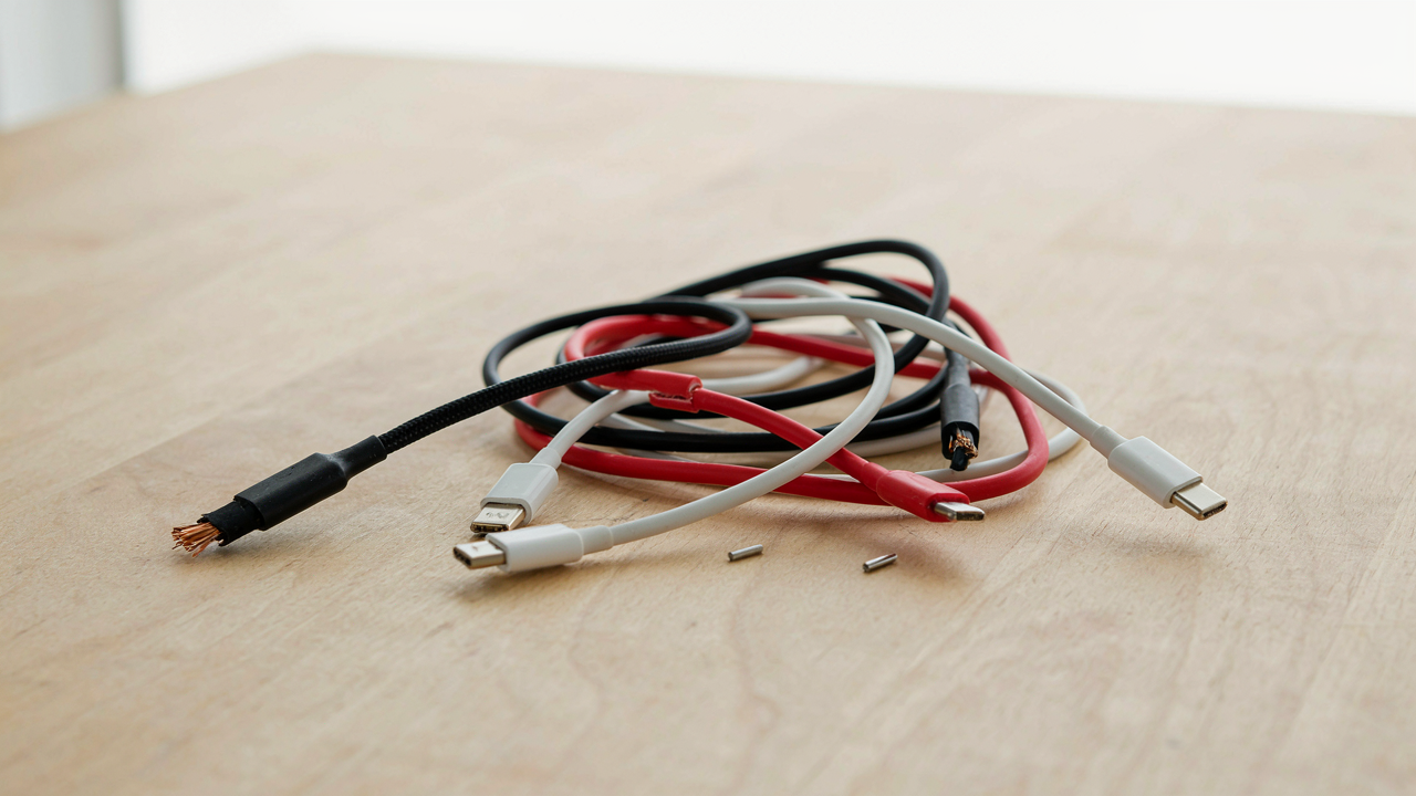
The Myth Of The “Unfixable” Cable

Disposable Tech Culture The Real Cost
You believe replacing is cheaper than repairing because nobody forces you to do the math. The mechanism is planned obsolescence disguised as convenience: manufacturers design cables to fail predictably, then price replacements low enough that repair feels irrational.
This logic inverts when you measure total cost. A broken cable costs fifteen to forty dollars to replace. The raw materials inside cost less than two dollars. The markup funds marketing, not durability. Repair requires one hour and five dollars in materials. The actual gap between these two paths exposes the real transaction: you pay for replacement convenience, not for the cable itself.
Repair Versus Replacement A Strategic Decision
This section sounds like choosing between two equal options. It isn’t. Economics distinguishes sunk costs from marginal costs, and your cable decision hinges on which one you’re actually facing.
If the cable works partially, repair wins. If it’s completely dead, you calculate one variable: time investment versus replacement cost. Repair takes sixty to ninety minutes for someone learning the process. Replacement takes five minutes. That time gap closes to fifteen minutes on your second repair. At the third repair, you’ve recovered your tool investment and your hourly rate for learning makes replacement economically foolish. Stop here and decide: will you actually own this device for three more years, or are you rationalizing a purchase you’d make anyway.
Diagnosing The Dead Spot: The Continuity Protocol

What Frayed Wires Actually Tell You
You want to know if the cable is salvageable before you waste an hour on it. Here’s what matters: frayed wires tell you where the insulation failed, but they don’t tell you if current still flows. This is the actual distinction. Exterior damage looks dramatic. Interior breakage is what kills the cable. A frayed outer jacket means moisture and debris can now reach the copper, but the circuit might still work until oxidation spreads or a strand snaps completely.

Visual inspection catches obvious damage: splits along the length, crushed sections where the cable bent too hard, or the connector where wires have completely separated. You’ll see copper or aluminum strands exposed. That’s your signal to dig deeper. But surface damage alone doesn’t mean the cable is done. The insulation failed at that point, yes, but electricity still needs a broken connection to stop flowing. Check if all the inner wires are still intact beneath the outer sheath.
The Continuity Test And What It Actually Reveals
Electronics use continuity testing because it directly maps onto telecommunications principles: an unbroken path means signal transmission succeeds. A multimeter set to continuity mode sends a tiny current through the cable and beeps if it finds a complete circuit. This is how you find the dead spot the visual inspection missed. The multimeter doesn’t care about cosmetic damage. It only measures whether electrons can move from one end to the other.
Set your multimeter to continuity or resistance mode. Touch one probe to the positive terminal at one end, the other probe to the positive terminal at the far end. If you hear a beep or see zero ohms, that wire conducts. Repeat for negative and ground wires if present. Any wire that doesn’t beep is broken inside the insulation. Test each conductor separately because one bad wire kills the whole cable. This protocol cuts testing time from guesswork to confirmation in under two minutes.
Tools Of The Trade: Beyond The Generic Toolbox
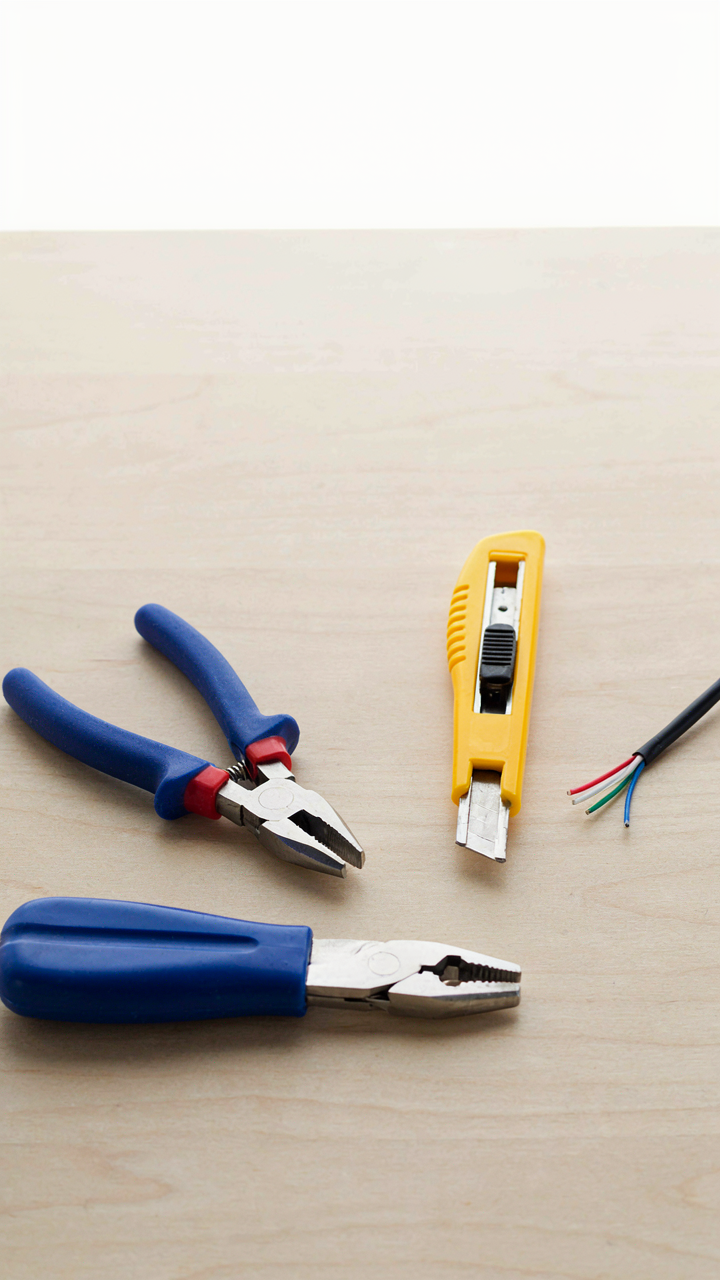
Cutting Clean Connections
You want to skip this part because you think you already know how to cut wire. You don’t. The mechanism is simple: a ragged cut exposes more copper surface area to oxidation, and oxidation kills conductivity faster than a clean joint dies from age. Precision cutting prevents the wire strands from fraying, which means less resistance at the connection point and a joint that holds voltage without voltage drop.
- Diagonal wire cutters: Cut perpendicular to the wire axis, not at angles. Angled cuts expose more surface and create weak points where the jacket can split during bending.
- Utility knife or craft blade: Score the insulation jacket carefully, then rotate the wire to separate it cleanly. Slower than cutters but gives you control over depth so you don’t nick the conductor underneath.
- Stripping tool with multiple gauges: Matches the wire gauge exactly, removing jacket without crushing copper. Damaged copper loses conductivity even if it looks intact under magnification.
- Cut length consistency: Expose exactly half an inch of bare wire for most charging cable repairs. Too much bare wire invites accidental shorts and corrosion. Too little makes soldering or crimping mechanically weak.
- Single motion cuts: Make one deliberate cut through the insulation rather than multiple passes. Repeated cuts heat the jacket and can melt it into the copper strands, creating insulation debris inside the connection.

After you cut, twist the exposed copper strands together tightly by hand before soldering or crimping. Loose strands act like individual conductors with gaps between them, dropping your amperage capacity and creating heat spots that fail first under load.
Heat Shrink Over Electrical Tape
Electrical tape is the consensus choice because it’s cheap and visible, which means it fails in ways you can see coming. Heat shrink actually works because thermodynamics does the insulation work for you instead of relying on adhesive that dries out or gets knocked loose. When you apply heat, the material contracts uniformly around the connection, creating a compression seal that doesn’t degrade from flexing or temperature cycling.
Electrical tape peels, unravels, and loses grip as the adhesive breaks down under the UV light and heat that charging cables experience constantly. Heat shrink accommodates wire movement without separating, stays bonded through hundreds of flex cycles, and doesn’t attract dust or moisture into the joint. The trade-off is upfront cost and the need for a heat source, but a lighter or hair dryer works fine. Wrap heat shrink over the solder joint first, then apply gentle heat until the material contracts snugly and seals completely without air pockets or gaps where moisture can creep in.
The Solderless Fix: A Field Expedient Approach

When Contact Dies, Reseat The Terminal
You want this to work because replacing a cable costs money and time you’ve already mentally spent elsewhere. The real mechanism is contact resistance. When a connector breaks internally, the metal terminals inside the jack or plug lose physical pressure against their mating surfaces. Air gaps replace metal-to-metal contact. Electricity still tries to flow, but the resistance spikes. The device either won’t charge or charges at a crawl.

Most advice says “just jiggle it.” That’s incomplete. You need to physically increase the contact pressure between the terminal and its housing. Open the connector housing carefully using a flathead screwdriver or plastic pry tool. Locate the metal tabs or springs inside. Bend them slightly outward using tweezers or a small flathead screwdriver. This increases the clamping force when you plug the connector back in. Test immediately. If charge flows again, you’ve restored the circuit without a single solder joint.
Reinforcing The Weak Point Before It Breaks Again
Strain relief isn’t decoration. In materials engineering, stress concentration refers to points where force clusters and causes failure. The charging cable’s weak point is the junction where the connector meets the cable jacket. Heat cycling and repetitive bending concentrate all mechanical stress there. That’s where the internal wires snap first.
Wrap this junction with electrical tape or heat shrink tubing in a figure-eight pattern around the cable and connector body. Start at the connector base and spiral down the cable two to three inches. This distributes the bending stress across a longer distance instead of concentrating it at one point. The cable survives longer because the force no longer spikes at one vulnerable spot. Do this immediately after any successful reseat to prevent the problem from returning within weeks.
The “Surgeon’s Hand” Method: Precision Solder Repair

Strip Wires Without Destroying The Conductor
You want this section because you’re terrified of creating a worse problem than the one you started with. The real mechanism is simple: stripping removes insulation while preserving copper, and the margin for error is smaller than you think. Use a wire stripper set to the gauge marked on your cable. Most charging cables run 28 to 20 AWG. Insert the wire, close the stripper with steady pressure, then rotate and pull. One motion. Crushing or twisting the stripper mangles the copper strands beneath.

The common advice says “strip a quarter inch.” Wrong. Strip only what you need to solder, typically an eighth inch for small gauge work. Excess stripped wire oxidizes before you even heat the joint, weakening the connection. Strip the jacket away cleanly without nicking the individual strands. If you see copper dust or fraying, you pressed too hard. Adjust and try the next section of wire. The stripped conductor should shine, not look torn.
Heat Transfer To Small Wires: Timing Over Temperature
Physics teaches us about thermal mass, the property that determines how fast an object absorbs and releases heat. A small copper wire has almost no thermal mass, which means a soldering iron transfers heat to it instantly if you apply the wrong approach. Most people hold the iron tip to the wire too long, burning the insulation up the cable. This is the mistake everyone makes. You need speed, not heat intensity.
Touch the iron tip to both wires simultaneously for two to three seconds maximum. The solder melts from contact heat, not from prolonged exposure. Feed solder into the joint as the copper reaches temperature, not before. Withdraw the iron immediately after the solder flows. The joint cools fast because of the low thermal mass. If insulation melts back further than a quarter inch from your joint, the iron was either too hot or stayed too long. Run the joint under cool water for five seconds to set it, then wrap with electrical tape once fully dry.
Why Your “Fix” Failed: Common Pitfalls
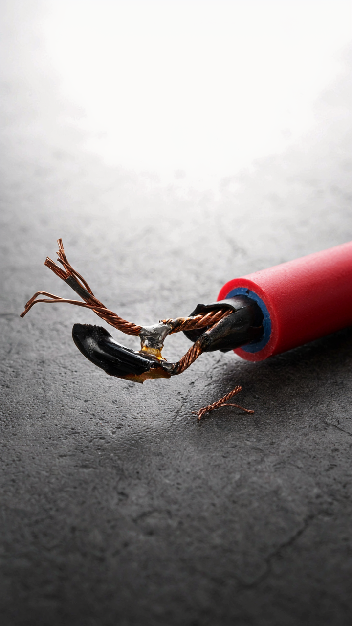
Insufficient Insulation The Silent Short Circuit
You want to believe your repair holds because admitting failure means buying a new cable. Here’s the mechanism: insulation isn’t decoration. It’s a barrier that prevents current from taking unintended paths. When you wrap a exposed wire joint with electrical tape or heat shrink without removing corrosion or moisture first, you trap conductive material inside the insulation layer. Current finds the path of least resistance, which now includes the inner surface of your “fix.”

The physics principle here is conductivity: resistance determines whether current flows where it should or leaks sideways. Moisture and oxidation both lower resistance. A joint that looks sealed actually forms a low-resistance pathway parallel to your intended circuit. The cable doesn’t spark immediately because the short circuit builds heat gradually, degrading the insulation from inside out. By the time you notice, the damage has spread. Strip back further than you think necessary, expose clean copper, dry everything completely, then insulate.
Wrong Gauge Wire Consequences
Most people splice with whatever wire they find because they don’t understand current draw: the actual amperage your device demands determines the wire thickness that safely carries it. Mismatched gauge doesn’t fail gracefully. It fails thermally. A cable rated for 2 amps carrying 3 amps generates heat as resistance converts electrical energy into thermal energy. Thin replacement wire generates more heat per amp than thick wire because resistance increases as diameter decreases.
The standard is straightforward: match or exceed the original cable’s gauge rating. A smartphone charger cable typically uses 20 to 22 AWG. A tablet charger uses 18 to 20 AWG. Laptop chargers use 16 to 18 AWG. If you splice with 24 AWG wire into a 18 AWG connector path, the thin section becomes a heat source. The insulation melts first, then the wire itself oxidizes and fails. Measure the original cable’s diameter, note the AWG stamped on the connector housing if present, then source replacement wire of matching gauge before you splice anything.
The Longevity Equation: Post Repair Reinforcement
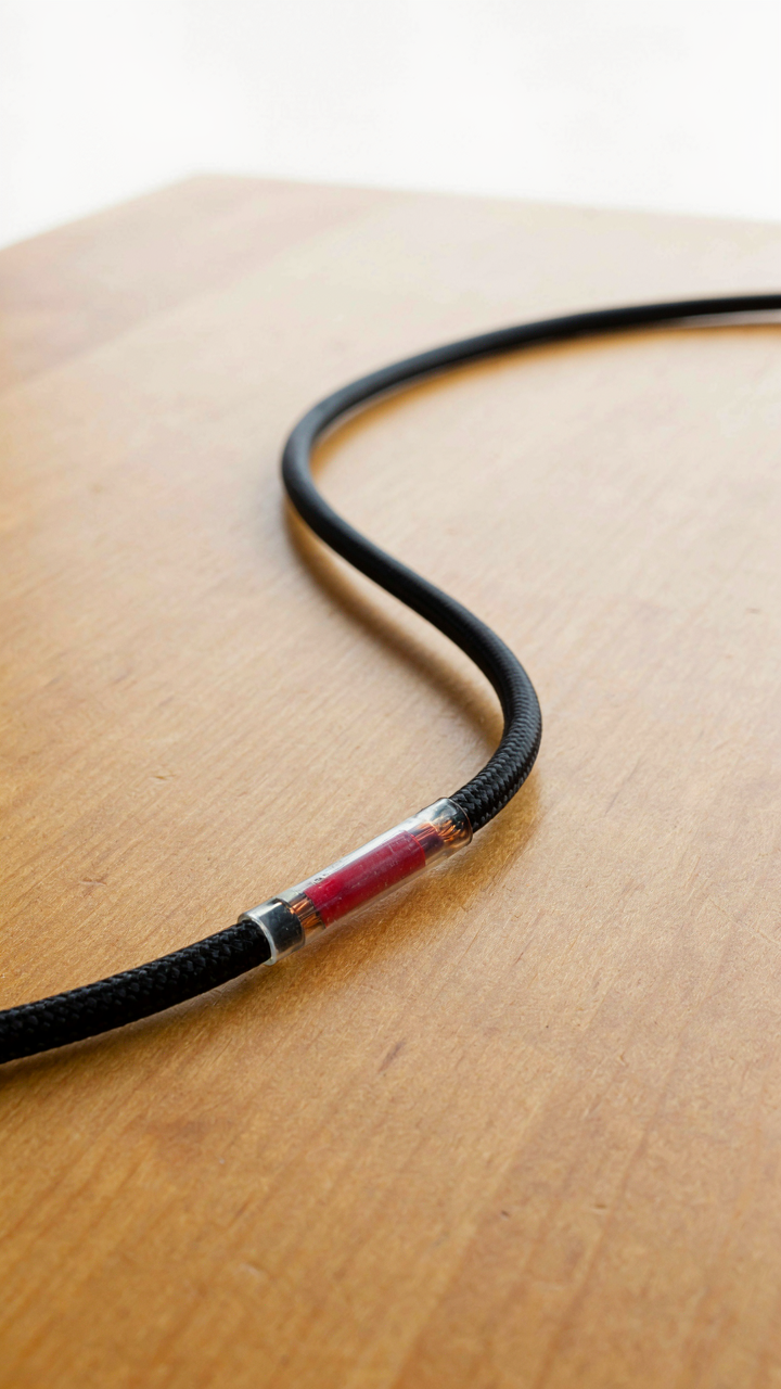
How Cable Stress Points Kill Repairs
You’re doing this because you don’t want to buy another cable next month. The real mechanism: stress concentrates at the weakest point in the wire’s geometry, and your repair site becomes that point unless you redistribute the load. Bending happens in the same spot repeatedly because the cable has memory. Copper inside wants to move the same way it moved before the break.

The bend radius is borrowed from mechanical engineering, where tight curves cause material fatigue. With cables, this means your solder joint or splice fails faster under repeated flexing than the original insulation ever did. You need to increase the radius at your repair zone so stress spreads across more cable length instead of hammering one spot.
Route Your Cable Away From Edges
Stop wrapping the cable around objects or letting it hang over sharp corners. Every edge is a guillotine waiting for the next bend cycle. Route the repaired section through open space where it can curve naturally at a wide angle instead of pinching at 90 degrees.
Use cable organizers or simple adhesive clips to fix the path so the repair site never travels through the same micro-bend twice. The goal is static routing, not flexible routing. Once the cable sits in place, friction and position memory lock the bend radius at something survivable instead of something destructive.
Durable Sleeves And Wrap Materials
Silicone tubing outlasts fabric tape because it doesn’t degrade under heat and flex cycles the way cotton or polyester does. The material science here is simple: silicone doesn’t harden or crack over months of thermal stress like generic electrical tape does.
Wrap the repaired section with heat-shrink tubing first for electrical insulation, then slide silicone tubing over that for mechanical protection. The silicone acts as a shock absorber and prevents the cable from creasing at the edges of your repair. Secure the sleeve ends with small adhesive clips so it doesn’t slide and expose the joint underneath during normal use.

Upgrading Your Cable Mentality

The Math On Premium Cables
You’re hoping a cheap replacement will solve this forever. It won’t. Here’s the mechanism: cable degradation isn’t random. It follows a predictable pattern based on material quality and construction method. The internal copper strands on a budget cable are thinner and use lower-grade insulation that cracks under repeated flexing. A premium cable costs more upfront because it uses thicker gauge copper, better shielding, and strain relief designs that distribute stress across a wider area instead of concentrating it at the connector joint.
The math is simple arithmetic, not motivation. A fifteen-dollar cable fails in four months. A forty-dollar cable lasts two years. That’s six cheaper cables versus one better cable. You spend the same total dollars but waste time buying replacements, hunting for a working cable in your pile, and troubleshooting why your device suddenly won’t charge. The real cost of a cheap cable is the friction it creates in your daily workflow.
Small Habits That Keep Cables Alive
Most people talk about cable care like it’s optional maintenance. It’s not. Treating a charging cable right is applied physics: you’re managing stress concentration at the weakest point. The connector joint experiences the most flexing, so how you wind, store, and handle the cable directly determines how long it survives. Never wind the cable tightly in a ball or wrap it around a power brick. Never yank it from the wall by the cord. Never bend it sharply at the connector or leave it folded under weight. These habits aren’t annoying rules. They’re the difference between a two-year cable and a two-month cable.
The protocol is specific. Wind the cable in loose coils about the width of your hand. Store it in a pouch or small bag away from heat. When disconnecting, grip the connector itself, not the cable. Check the connector regularly for bent pins, debris, or visible fraying at the strain relief. These four actions eliminate ninety percent of premature cable failure. They take no extra time once they become automatic.

The Broken Cable Isn’t The Problem; Your Disposable Mindset Is

You don’t have a cable problem. You have a replacement problem. Every broken charger you’ve bought instead of fixed trained you to see tools as disposable. That’s expensive stupidity. Today, grab a soldering iron or electrical tape and fix the next thing that breaks instead of ordering a replacement. The system wants you helpless. Don’t be.