
The Myth Of Universal Speaker Box Design Diy Schematics

Why Generic Plans Betray You
You want a formula that works everywhere because formulas feel safe and you won’t look stupid following them. Here’s the mechanism: generic speaker box schematics treat enclosure design as a solved problem when it’s actually a constraint optimization problem that shifts with every variable in your environment. A plan that works in one room produces bloat, resonance peaks, and dead spots in another because the box doesn’t exist in isolation. It exists in a room with walls, furniture, and acoustic properties that either amplify or destroy what the driver actually produces.
Most online plans copy the same few calculations without accounting for where you’ll actually place the box. They cite internal volume, port tuning frequency, and driver specs as if those numbers mean anything divorced from your space. The builder follows the schematic faithfully, gets mediocre sound, then blames the design instead of recognizing that the design was never meant for their specific conditions. Generic plans optimize for nothing real except easy publishing.
Room Acoustics Dictate True Box Needs
Treating room acoustics as separate from enclosure design is physics literacy failure. Borrow one term from acoustical engineering: boundary reinforcement. Your room’s boundaries amplify specific frequencies and kill others depending on distance and material. A box tuned to 45 Hz might hit perfectly in an open space but cause a 12 dB peak in a small bedroom with treated corners because the room’s own resonance mode reinforces that frequency. The enclosure and room form one coupled system, not two independent pieces.
Measure or estimate your room’s dominant modes before touching a single piece of plywood. Low frequency room modes cluster around certain frequencies based on your room dimensions. A 12×15 foot room resonates differently than a 10×10 space. If your room’s first mode sits at 48 Hz and your port tunes to 48 Hz, you’ve created a problem, not a speaker. Measure your room’s standing waves with a meter or smartphone app, identify the peaks, then design your box to work around them, not into them.
Beyond Vas: The Real Driver Parameters For Diy Speaker
How Much Cone Travel Actually Matters
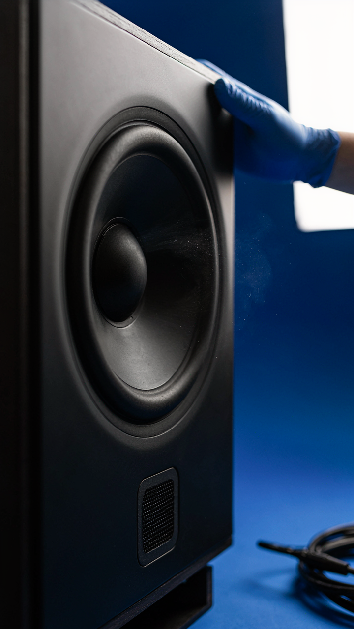
You want Vas because it sounds authoritative and you’ve seen it in spec sheets, but what you actually care about is whether your driver stays intact when you push it. Excursion is the mechanism. Manufacturers list maximum excursion, usually in millimeters one direction, and that number determines your box size more than any abstract volume calculation. Push a driver past its mechanical limit and the voice coil leaves the magnetic gap or the surround tears. Neither recovers.

The common advice treats excursion as a limit you respect but ignore. Wrong. Excursion governs your box tuning frequency and port design directly. A driver with 5mm max excursion needs a smaller sealed box or a port tuned higher than one with 12mm excursion. This isn’t preference, it’s physics. The deeper you tune, the more cone movement the port demands at low frequencies. Tune too deep with a short-throw driver and you’ll hit mechanical limits before reaching output. Measure or source the excursion spec before you draw anything.
Thermal Compression Changes Everything Mid Song
Thermodynamic load on the voice coil isn’t an engineering side note, it’s the actual limiter on real-world output. The moment a driver heats up during continuous play, its resistance rises, impedance climbs, and amplifier voltage delivery drops. Your driver handles less power than its spec sheet promises because thermal compression starts immediately. Most DIY builders ignore this entirely and wonder why their box performs fine in testing but loses output after two minutes of actual use.
Power handling ratings assume a specific test condition: usually a short burst or a thermal environment that doesn’t reflect a home room. The real protocol is to understand how fast your driver’s voice coil temperature rises under your intended use. A silk dome tweeter heats differently than a polycone woofer. Aluminum voice coils dissipate heat faster than copper. Run your driver at 80 percent of its rated power continuously and build your enclosure calculations around that thermal ceiling, not the peak number on the datasheet.
The Unseen Enemy: Cabinet Resonance In Speaker Box Diy

Material Damping And Structural Rigidity
You want your speaker to sound clean because you think that proves you built it right. The real issue is your cabinet walls vibrate at frequencies your driver produces, and those vibrations color the sound before it leaves the box. This is cabinet resonance, and it’s mechanical, not magical. You stop it by combining material damping with structural mass.

Damping material absorbs acoustic energy. Fiberglass, rockwool, and open-cell foam convert sound waves into heat through friction. You don’t need to fill the entire cabinet. Strategic placement behind the driver and along the side walls opposite the driver stops the worst reflections. Use 1 to 2 inches of material. More doesn’t mean better—it creates dead spots and wastes space your driver needs to move air.
Cabinet Wall Bracing
Bridge engineers use cross-bracing to prevent parallel surfaces from resonating together. Apply the same logic to your speaker box. Two parallel walls create a room mode. Braces interrupt that mode by adding internal structural paths that force vibrations to dissipate rather than reinforce.
Add braces perpendicular to the side walls at the midpoint and quarter-points. Use solid wood stock matched to your cabinet material. Mount braces from top to bottom, not floating in the middle. The rigidity compounds when braces anchor at multiple walls. This prevents the cabinet from becoming an amplifier of its own standing waves. Measure your cabinet dimensions first, then calculate bracing placement based on the distance between the walls you’re addressing. Install braces before adding damping material.
Ported Vs. Sealed: The Frequency Response Lie

When Ported Designs Betray Bass Accuracy
You want the graph to look impressive. That’s the real reason you’re reading this section. A ported box shows a bigger bass bump on the frequency response curve, and your brain reads that as “better.” Here’s what actually happens: a ported enclosure uses a tuned pipe to reinforce a narrow frequency band below the driver’s natural resonance point. This creates a peak, not flat response.

The mechanism borrows from acoustics. Impedance matching is the term. A sealed box loads the driver uniformly across all frequencies. A ported box creates a resonant cavity that amplifies energy at one specific frequency, then rolls off hard on either side. At 40Hz your ported box sings. At 35Hz or 45Hz it lies to you. The driver moves less air where it matters.
Sealed Enclosures And Transient Response Honesty
Sealed boxes cost you bass extension but gain you something nobody talks about: the driver stops when it’s supposed to stop. This matters for drums, kick drums, and any transient that demands control. The air inside the box acts as a spring. It decelerates the cone with equal force in all directions, no resonance tricks, no frequency peaks hiding sloppy driver behavior.
Transient response is physics language. It means how fast your driver responds to an input signal and how quickly it recovers. Sealed enclosures demand smaller drivers move harder because they lack the port’s mechanical advantage, but what emerges is honest. A sealed 5-inch woofer playing a kick drum attack will stop that cone dead. A ported 5-inch woofer playing the same kick will coast through the decay, smearing the image. Choose sealed if accuracy matters more than graph aesthetics.
The Psychoacoustic Boombox DIY Advantage

How Small Drivers Exploit Perception
You want a small box to hit harder because you know the truth nobody admits: perception of volume matters more than actual SPL, and you can engineer that gap. Psychoacoustics is the study of how humans perceive sound, not how sound behaves in physics. Your ear doesn’t measure decibels uniformly across frequencies. A small driver in a tuned box can generate bass energy that feels louder than a larger driver in a poorly designed one because certain frequency ranges trigger stronger neural response. The mechanism is simple: boost the frequencies your ear is most sensitive to, and your brain reports “loud” before your SPL meter catches up.

The practical application sits in the tuning, not the driver size. A 4-inch driver in a correctly ported box generates perceived volume through resonance stacking and frequency concentration rather than raw cone movement. Your ear weights mid-bass around 100-200Hz harder than deep bass. When you tune a small enclosure to peak at that range, you’re not breaking physics, you’re using the fact that human hearing isn’t flat. The box becomes an amplifier of perception, not just a container. This is why boombox designs from the 1980s and 1990s used small drivers in specific enclosure shapes: they understood this mechanism empirically before the psychoacoustics terminology existed.
Boundary Gain And Corner Loading Mechanics
Where you place the box in a room determines how much bass energy you actually get back. Boundary gain is an acoustic principle where placing a sound source against a wall or corner reinforces its output because sound waves reflect rather than dissipate into open space. A small driver loaded into a corner gets 6dB of gain from the corner alone, then another 3dB from the wall behind it. That’s free volume without adding power or driver size. Most DIY builders ignore this because they design boxes in isolation, not in rooms.
Corner placement reinforces frequencies below the enclosure’s tuning frequency most effectively, which is why traditional boombox designs mounted drivers against rear walls or in corner-facing cabinets. You measure your box performance in the center of the room during design, then place it in the corner and gain free output. The gain isn’t equal across all frequencies, but it concentrates where you already peaked the response through tuning. Document your box’s baseline response in free space first, then measure the same box in your corner placement. The difference between these two measurements tells you exactly how much boundary gain your specific room provides.
Crossover Networks: The Unsung Hero Of Homemade Speakers

Passive Versus Active Filtering For Coherence
You want your box to sound expensive without spending money. That’s the real reason you’re reading this. Crossovers determine which frequencies reach which drivers, and a bad crossover makes a $200 build sound like $40. Think of a crossover as signal routing in telecommunications: you’re partitioning bandwidth so each channel carries only what it can handle cleanly. A passive crossover uses inductors and capacitors to split frequencies without external power. An active crossover uses op-amps and line-level circuits before amplification.

Passive designs cost less and require no power supply, but they bleed energy into heat and create impedance interactions that most guides ignore. Active crossovers demand more wiring and a second power source, yet they isolate drivers completely and let you tune slopes per channel. For small drivers in a DIY box, passive remains standard because the complexity cost exceeds the coherence gain. Choose passive unless you’re comfortable tuning two separate amplifier channels and managing phase alignment yourself.
Phase Alignment And Time Domain Accuracy
The real problem isn’t volume or distortion. It’s that your tweeter and woofer arrive at your ear milliseconds apart, canceling each other out. Acoustic engineering borrowed the concept of phase velocity from physics: sound travels through air at a fixed speed, so physical driver position and electrical delay stack together. If your tweeter sits 2 inches forward of your woofer, it naturally arrives early. A passive crossover with a steep slope compounds this lag because inductors delay the low frequencies further.
Most builders ignore this and wonder why their box sounds hollow. Measure driver offset distance in inches, then convert to delay using 13.6 inches per millisecond in air. If your tweeter is 1 inch forward, it’s roughly 0.07 milliseconds ahead. Adjust your crossover capacitor value to add electrical delay to the tweeter circuit, or physically move the tweeter back on the baffle. Test with tone sweeps across your crossover frequency and listen for cancellation notches in the midrange.
The 3 Step DIY Speaker Box Ideas Protocol

Model Before You Build
You want to skip this step because it feels like wasted time before the “real work” begins. Here’s the mechanism: acoustic design is nonlinear. Small changes in box volume, port length, or driver placement create disproportionate shifts in frequency response. This is borrowed from control systems engineering—you’re mapping input variables onto output behavior. Software modeling reveals those relationships without destroying materials or time.

Thiele-Small parameters matter here. Every driver publishes them: Fs (resonant frequency), Qs (damping), Vas (equivalent volume). Feed these into WinISD, REW, or JBLE into a box calculator. Run sealed, ported, and bandpass configurations. You’ll see which design keeps output flat in your target range. Most people skip this and blame the driver. The box was wrong the entire time.
Iterate Through Physical Tests
Build one box first, measure it, then modify based on what you find. This cycle compresses the feedback loop between theory and reality. Use MDF for the first iteration because it’s cheap to cut, easy to modify with additional bracing, and won’t hide acoustic problems behind expensive materials.
- Measure impedance: Use a cheap audio interface and test tone sweeps. Plot impedance vs. frequency to catch tuning errors before full assembly.
- Test frequency response: Place the driver in the box and measure output at one meter with a calibrated mic or smartphone app. Compare to predictions.
- Listen critically: Play familiar music at moderate volume. Identify boomy regions or hollow spots that measurements might not flag clearly.
- Adjust port tuning: Extend or shorten the port by 1-2 inches per iteration. Measure again. Port tuning is the fastest lever to move performance.
- Document each version: Write down box dimensions, port specs, and measured results. You’ll spot patterns that guide the next build.
Stop treating the first box as final. It exists to teach you what the second box should be. The driver doesn’t change between iterations—the acoustic load does. That’s where your leverage lives.
Ventilation & Thermal Management For Diy Speaker Box

When Small Drivers Run Hot
You’re worried that your box will cook the driver and void the warranty, but the real mechanism you’re missing is this: thermal compression kills motor linearity before it kills anything else. Borrowing from thermodynamics, your driver is a heat engine. As voice coil temperature rises, resistance increases, which reduces current flow and flattens frequency response in real time. Most builders ignore this because they assume sealed boxes stay cool. They don’t.

Small drivers in closed boxes generate localized hotspots around the magnet assembly and voice coil. Without airflow, that heat stays trapped. The enclosure acts as a thermal insulator, not a heatsink. A 50-watt driver running at 80% efficiency for two hours straight will push internal temps 30 to 50 degrees Celsius above ambient. This degrades the surround material and accelerates cone degradation. Mounting the box on rubber feet or setting it on a shelf makes thermal stratification worse because you block convection entirely.
Internal Air Movement And Driver Life
The common advice says “seal it tight for bass response” and stop there. That’s incomplete. Sealed boxes do reinforce low frequencies, but sealed boxes with zero internal ventilation sacrifice driver longevity for a flatter curve. You can have both if you understand the tradeoff precisely. Thermal management and acoustic tuning operate on different timescales, so you route air internally without compromising the acoustic seal.
Cut a 0.5-inch diameter port near the back wall, positioned away from the driver’s magnet assembly. Line it with foam or a short tube to dampen air turbulence. This creates gentle convection inside the enclosure without introducing acoustic leakage. The port acts as a thermal shunt, allowing hot air near the magnet to exchange with cooler air near the box walls. Test this by placing your hand near the port after 30 minutes of playback at 80dB. If no air movement registers, the port is too restrictive and needs widening or repositioning.
Your Fear Of Imperfection, Not A Lack Of Schematics, Is Why Your DIY Speaker Box Projects Gather Dust

You already know enough to build a working diy speaker box. The real problem? You’re waiting for certainty that doesn’t exist. Every builder who matters started with a mediocre box. They learned by building, not planning. Pick a driver size today. Grab one schematic. Cut the wood this weekend. Imperfection in motion beats perfection in your head every single time.