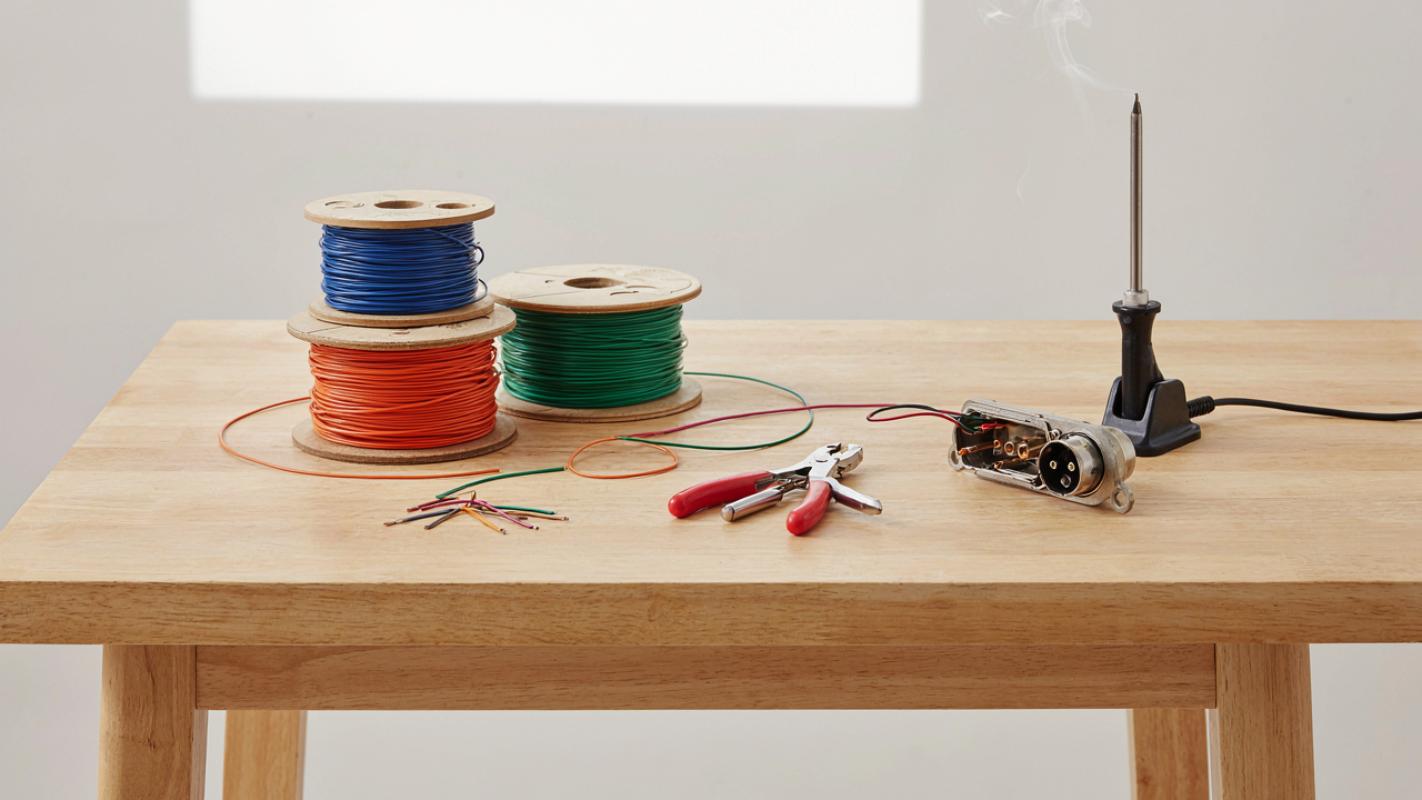
The Myth Of Exotic Materials: Your Wallet Is The Weakest Link
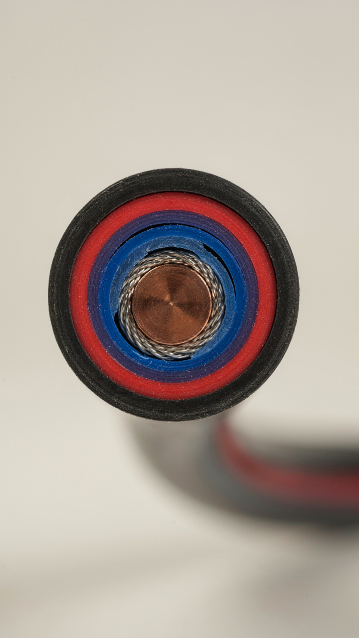
When Conductor Purity Stops Mattering
You want to believe that spending more on pure copper or silver solves the problem because it means you’re doing it right. Here’s the mechanism that matters: conductor purity follows an economics curve, not a performance curve. After 99.9% purity, you’re buying diminishing returns measured in fractions of a decibel that don’t exist in your listening environment’s noise floor.
The audio industry learned this in the 1980s when oxygen-free copper became standard. Going beyond that standard adds cost with zero measurable electrical benefit in frequencies below 100 kHz. Your cable runs through walls, near power lines, and past interference sources that dwarf whatever marginal resistance reduction ultra-pure materials provide. Spend the money on proper shielding and connector quality instead.
Insulation Is About Impedance, Not Magic
The common advice is that cable insulation changes your sound. It doesn’t. Insulation serves one job: controlling impedance consistency across the cable run. This is engineering, not alchemy. Polyethylene, PVC, and Teflon all work because they keep the capacitance stable between the conductor and shield.
What actually matters is that your insulation thickness remains uniform and your shield geometry stays constant. A poorly extruded cable with uneven insulation will have impedance variations that cause reflections at certain frequencies. Buy insulation material from a reliable supplier and check tolerances during construction, not the brand name on the spool.
The Connection Integrity Protocol: Beyond Solder Points

Terminal Selection: Mechanical Advantage Over Mysticism
You want to believe the solder joint is what matters. It isn’t. Borrowed from mechanical engineering, the concept of “stress concentration” applies directly here: terminals distribute force across a wider contact area, and a poor terminal choice creates a point of failure that no solder can fix. Most DIY builders grab whatever connector fits the wire gauge and call it done. That’s the mistake. Terminal selection determines how current actually flows and how pressure stays consistent over years of thermal cycling and cable movement.

The terminal’s crimp geometry controls everything. A terminal with shallow contact fingers won’t grip stranded wire uniformly, leaving high-resistance paths. A terminal with no strain relief shoulder lets the wire bend sharply at the crimp point, fracturing strands before they even reach solder. Choose terminals rated for your exact wire gauge, verify the crimp tool matches the terminal specification, and crimp before soldering. The crimp does the mechanical work. The solder just adds redundancy.
Strain Relief: Preventing Micro Fractures
Everyone solder-soaks the joint and walks away. That’s how cables fail at the exact point you touch them. Strain relief isn’t decoration. It’s a load path that redirects flexing stress away from the solder joint itself, which is brittle and cannot tolerate repeated bending. A proper strain relief—whether heat shrink tube with internal support, a molded boot, or a hand-formed solder bridge—must span at least half an inch from the terminal and transition gradually into the cable jacket.
Micro-fractures begin with micro-movement. Each flex introduces a tiny crack in solder, invisible to sight but measurable by intermittent signal dropout or channel imbalance. Install strain relief before the solder fully cools so it makes contact with the joint immediately. The strain relief absorbs the bending load so the solder doesn’t have to. Test the finished cable by flexing it sharply near the connection point ten times. If it survives that, the strain relief geometry is correct.
DIY Speaker Cable: Gauge, Length, And The Physics Of Resistance
How Resistance Kills Your Signal
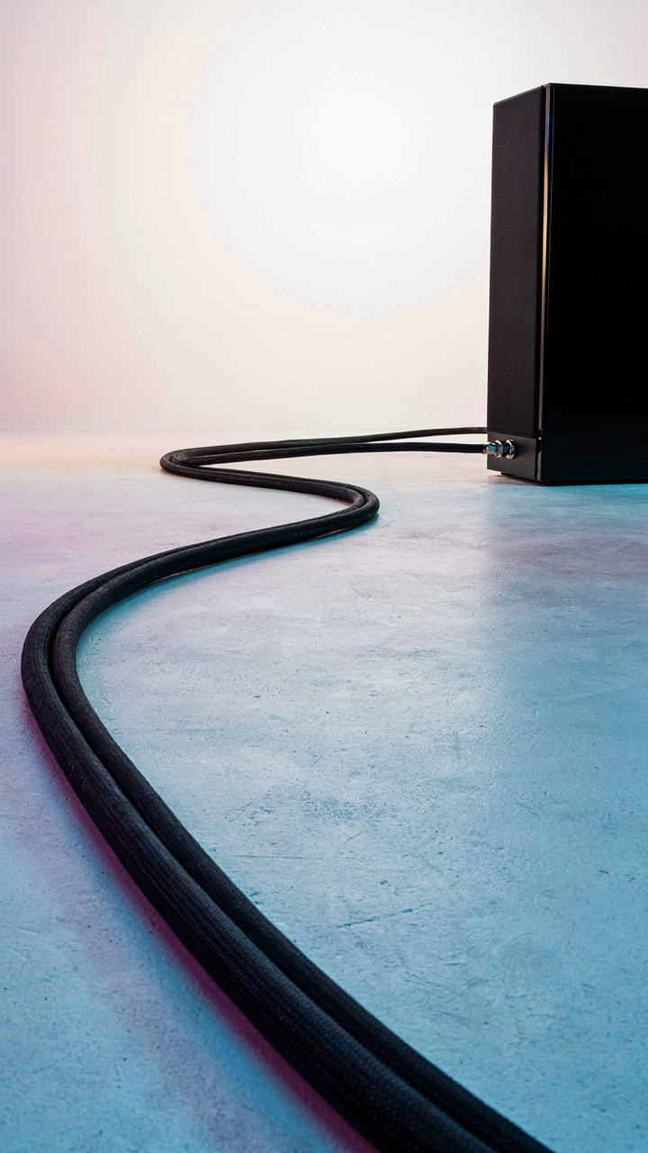
You care about this section because you want to believe your cable choice matters more than it actually does. The truth is simpler: resistance is just friction for electricity, and physics doesn’t negotiate. Wire diameter and length determine how much resistance your cable introduces. Thicker wire moves current with less opposition. Longer runs accumulate more resistance. Ohm’s Law quantifies this relationship: voltage drop equals current multiplied by resistance. For audio, voltage drop means your amplifier’s power reaches the speaker diminished. This matters in short runs only under specific conditions.

Gauge measures wire diameter using the American Wire Gauge system, where lower numbers mean thicker copper. A 4 AWG speaker cable has roughly double the cross sectional area of 8 AWG, cutting resistance in half. Resistance per foot varies by gauge and copper purity. Calculate total cable resistance by multiplying the per-foot value by your total cable length, then multiply by two to account for both conductors. Most DIY builders stop thinking here and wire whatever feels thick. That’s lazy. What matters is the ratio between your cable resistance and your speaker’s impedance. A typical 8-ohm speaker with 50 feet of 14 AWG cable introduces roughly 0.05 ohms of resistance. This is negligible noise compared to 8 ohms.
When Skin Effect Actually Applies
Skin effect is real physics borrowed from electrical engineering, but applying it to speaker cables is where most cable mythology lives. At audio frequencies, skin effect describes how high frequency current concentrates toward the outer edge of a conductor rather than distributing evenly throughout. This happens because the conductor’s magnetic field opposes current flow in the center. The effect intensifies with frequency and conductor diameter. For speaker cables carrying signals below 20 kHz through thick copper, skin effect is so minor it vanishes inside measurement error. You don’t fight it by using hollow or braided conductors. That’s marketing dressed as engineering.
The mistake: people reference skin effect to justify exotic cable construction when the real culprit is usually improper shielding, poor connectors, or proximity to interference sources. Speaker cable isn’t balanced like XLR interconnect, so it can’t reject noise the same way. At audio frequencies through standard wire, the skin effect depth extends far deeper than the conductor itself. Use solid core copper of appropriate gauge for your distance, terminate it cleanly to your amplifier and speaker, and move on. Measure voltage at the speaker terminals before and after your cable run with a multimeter under load if you need proof the cable isn’t the problem.
DIY RCA Cables: Shielding From The Unseen Warfare Of EMI
Braid Versus Foil: What Actually Stops Interference
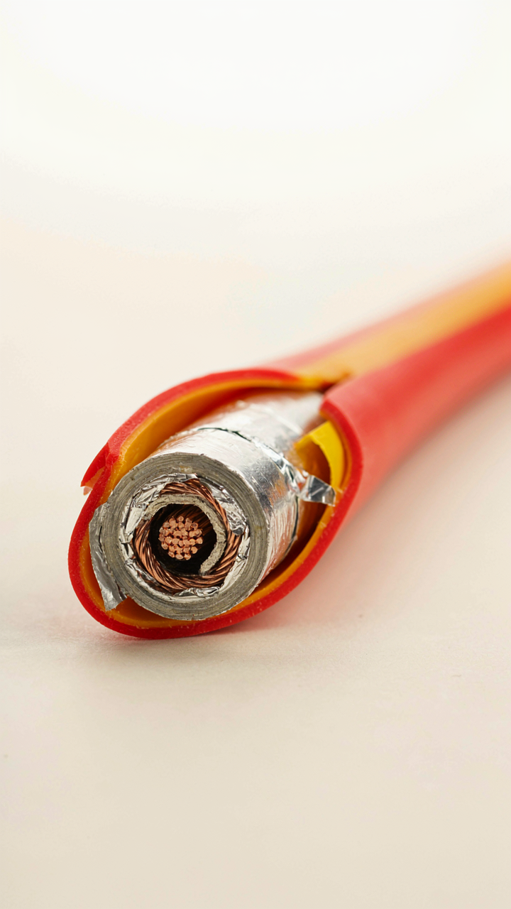
You want your cables to work like they cost three hundred dollars because you believe the equipment deserves it. Here’s the mechanism: electromagnetic interference operates like military jamming—the enemy broadcasts noise across a frequency band, and your unshielded signal gets corrupted. Braided shield and foil shield stop this through different physics. Braid uses interlocking copper strands wrapped helically around conductors. Foil uses a thin aluminum or copper layer pressed flat against the jacket.

Braid offers superior coverage above 1 MHz because the gaps between strands still attenuate high-frequency noise effectively. Foil provides near-complete DC continuity and low-frequency rejection but fails above 10 MHz due to pin-hole leakage through the material. The common advice—”braid is always better”—is incomplete. For audio RCA cables running under 20 kHz, foil alone stops 90 percent of real-world hum. Combine foil with a drain wire for the remaining margin. Braid matters when you’re running cables near switching power supplies or RF sources. Most home setups don’t have that problem.
Ground Loops: The Wiring Scheme That Kills Hum
Hum loops form when two separate grounding paths create a closed loop and AC current flows through it instead of to earth. This isn’t a mystery—it’s Kirchhoff’s law applied to your cable. Your RCA shield connects to the preamp chassis ground at one end and the amplifier chassis ground at the other. If both chassis also ground to the wall outlet, current takes the cable as a shortcut, inducing 50 or 60 Hz into your audio path.
The solution is single-point grounding: connect the RCA shield to ground at only one endpoint. In practice, ground the shield at the preamp side and leave it floating at the amp side. This forces hum current to follow the wall ground instead of your cable. Use a star-grounding layout in your chassis to prevent parallel paths that recreate the loop. The shield drain wire should terminate at a single point on the chassis, never split to multiple grounds. This eliminates the second path entirely.
Diy Audio Cable Setup: The Art Of Signal Path Hygiene
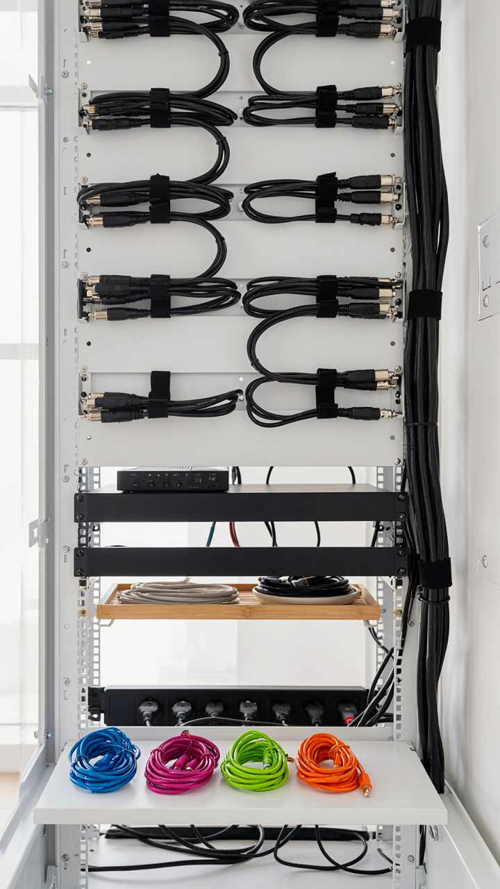
Keep Your Signal Away From Power
You want quiet cables because you think that means better sound quality, but the real motive is simpler: you don’t want to hear that you wasted money on gear that doesn’t perform. The mechanism comes straight from electromagnetics. Power cables radiate electromagnetic fields. Audio cables act as antennas and pick up that noise. Separation is the only fix that works reliably.

Route audio cables at least twelve inches away from power cables whenever possible. This distance gives the magnetic field room to collapse before it reaches your signal conductors. When separation is impossible, cross power and audio cables at ninety-degree angles rather than running them parallel. The crossing angle minimizes the coupled magnetic flux. Secure cables to prevent movement that changes capacitive coupling over time.
Balanced Cables Beat Twisted Pairs For Real
The common advice says twisted pair shielding solves crosstalk. It doesn’t. Balanced audio uses a rejection mechanism borrowed directly from communication theory called differential signaling. Your audio signal travels on two wires with opposite polarity. Noise couples equally to both wires. The receiving end subtracts one from the other, canceling the noise and leaving only your signal intact.
Unbalanced cables work fine for short runs under six feet, but crosstalk accumulates over distance. Use balanced XLR or AES connectors for any cable longer than eight feet or running near electrical noise sources. Twisted pair without balance just moves the problem around. Build balanced interconnects with separate outbound and return conductors using identical gauge wire and identical shield coverage on both conductors. This symmetry is what forces the noise rejection to actually function.
How To Make Rca Cables: The Surgical Precision Of Termination

The Stripping Decision That Ruins Everything
You want your cables to work without embarrassment. The truth is that most people strip wire wrong and never know it cost them signal integrity. Stripping damage mirrors metallurgy’s concept of work hardening: when you bend or score conductor material, you create stress points that degrade electrical flow before current even leaves the factory.

Use a dedicated wire stripper set to the exact gauge of your conductor, not a knife or your teeth. RCA cables typically use 20 to 24 AWG conductors. Strip only 6-8 millimeters of jacket. The mistake everyone makes is rotating the stripper or pulling at an angle, which scores the copper underneath. Pull straight and let the tool do the work. Untwist the strands gently after stripping. Any kinked or broken strand reduces your effective conductor cross-section and increases resistance.
The Joint That Holds Signal
Cold joints kill audio clarity and you won’t hear it as a problem until someone else’s cable sounds noticeably clearer. A cold joint means solder didn’t melt the copper fully, creating a high-resistance boundary that adds noise floor and reduces dynamic range. The mechanism is simple: solder bonds to copper only when both materials reach melting temperature simultaneously.
Heat the RCA connector pin for two seconds before touching solder to it. Use 60/40 or 63/37 tin-lead solder, not lead-free variants designed for circuit boards. Lead-free requires higher temperatures and creates grainy joints on audio connectors. Apply solder to the heated pin, not the iron tip. You’ll see it flow into the strands like water into sand. Remove the iron and let the joint cool without moving anything for five seconds. The joint should be shiny and cone-shaped, never dull or blobbed.
Diy Audio Cable Repair: Reviving Dead Connections, Not Replacing Them

When Continuity Fails: Find The Break
You want to believe the cable is fine because replacing it means admitting you wasted money or time. Continuity testing is where that denial ends. A multimeter set to resistance mode tells you if current flows end-to-end. If the needle doesn’t move or the digital readout shows open circuit, the conductor is severed somewhere inside the jacket. This is physics, not opinion: electricity requires a complete loop. No loop means no signal.

The break lives inside the strain relief, at the connector solder joint, or where the cable bends repeatedly at the same angle. Start testing from the connector back toward the cable body in short sections. Identify the exact zone where continuity drops. Once you know where the damage is, you can decide whether salvage makes sense. Most failures aren’t random. They follow predictable patterns based on how the cable was handled.
Re Terminate And Keep The Wire
Throwing away a six-foot cable because the XLR connector failed is wasteful engineering. The conductor inside is usually fine. Clip off the bad connector, strip the jacket back two inches, expose the twisted pair and shield, and solder a new XLR or RCA termination to clean wire. Common advice says this is risky. It’s not. It’s faster than buying new. You already know the cable’s impedance and wire gauge because you made it. Rebuild the termination to spec and move forward.
The re-termination process keeps the cable’s original character intact. You aren’t replacing conductor material or changing capacitance per foot. You’re restoring the signal path at a single point of failure. Strip carefully to avoid nicking the inner conductors. Use the same solder and flux you used on the first termination. Test continuity again, then run a short audio signal through the repaired section before full deployment. This method turns a dead cable into a working one in under fifteen minutes.
How To Wire Audio Cables: The Strategic Principles Of Military Logistics

Before You Buy Anything, Know What You Actually Need
You want to feel prepared. That’s the real reason you’re reading this section. But most people stockpile materials they’ll never use, then convince themselves they’re “ready.” Military logistics operates on a different principle: demand forecasting. You don’t move supplies until you know exactly what you’re deploying.

Map out every cable you’ll make in the next six months. Count connectors by type. Measure wire lengths for each run. This removes guesswork and prevents the amateur move of buying bulk quantities then discovering you grabbed the wrong gauge.
- Cable Inventory Sheet: List every cable project, connectors needed, wire gauge, and total length required before ordering anything.
- Connector Type Breakdown: Separate RCA, XLR, 1/4 inch, and any proprietary connectors into individual counts to avoid duplicate purchases.
- Wire Gauge Matching: Cross-reference impedance requirements for each cable type against the wire gauges you stock.
- Tool Readiness Assessment: Verify crimpers, strippers, and soldering equipment work before materials arrive.
- Storage Strategy: Plan shelf space for spools and connectors in sealed, climate-controlled conditions to prevent oxidation.
The goal is zero waste and zero delays. You order exactly what the next six months demand, nothing more. When material arrives, tools are already functional and space is already allocated.
Supply Chain Architecture: Bulk Ordering Done Right
Most DIY builders treat bulk purchasing like stocking a pantry. They don’t. In military supply chains, inventory velocity matters more than volume discounts. Slow-moving stock becomes a liability.
Buy wire in bulk only when you have committed projects in your pipeline. A 500-foot spool of 20AWG Mogami or Canare makes sense if you’re building ten balanced XLR cables over two months. It makes no sense sitting in your shop for a year. Connectors should turn over every three months minimum. Dead inventory attracts oxidation, dust, and decision paralysis.
- Bulk Wire Minimum: Purchase 250 to 500 foot spools only for wire gauges you use monthly, not quarterly.
- Connector Staging: Keep two to three months of connector stock on hand, ordered from suppliers with reliable lead times under two weeks.
- Batch Production Windows: Create cables in focused batches every four to six weeks rather than random single builds that waste setup time.
- Supplier Redundancy: Identify two reliable sources for connectors and wire to hedge against single-point supply failures.
- Quality Audits: Inspect incoming wire and connectors immediately for defects or oxidation before accepting delivery.
When new materials land, test a sample connector and wire segment immediately. This catches supplier inconsistency before you invest eight hours into a batch of bad cable. The mechanism is simple: frequent small orders with immediate quality verification beat rare large orders with delayed problems.

Three Types Of Speaker Cables: Beyond The Single Run Fallacy

Biwire Speaker Cable: Separating Frequencies
You want biwire because it sounds like a performance upgrade, but the real reason you’re drawn to it is control—the fantasy that splitting treble and bass paths eliminates crosstalk. Biwire works on a signal isolation principle borrowed from electrical engineering: lower impedance paths for different frequency bands reduce mutual interference. A biwire run uses four conductors instead of two, sending highs down one pair and lows down another, each terminating at separate binding posts on the amplifier and speaker.
The catch: biwire only works if your speaker actually has internal crossovers that separate those paths. Most speakers don’t. Run biwire on a speaker with a single internal crossover and you’ve wasted conductor material. If your speaker lists dual binding posts as true biwire capable, verify the internal wiring diagram. Use 12 or 10 gauge for the bass run and 14 or 12 for the treble run, since treble demands less current. Terminate both pairs cleanly at the amp end using separate banana plugs or spades, never daisy-chained connectors.
Coiled Audio Cable: Managing Excess Length
The common advice is to coil your excess cable neatly and call it done. This ignores the fact that coiled conductors generate inductance, which colors the signal by storing and releasing energy at specific frequencies. Excess cable needs containment, not just organization. Instead of random coiling, use a figure-eight coil method: loop the cable back on itself in alternating directions, which cancels the magnetic field your single loop would create.
Make coils no tighter than four inches in diameter. Wrap the coil loosely with hook-and-loop tape or cable ties spaced three inches apart to prevent the coil from collapsing into a dense spiral. Never use metal clamps or tie wraps that pinch the jacket. Position the coil away from amplifiers and power sources by at least three feet to avoid stray electromagnetic noise. Measure your actual run distance, then add twelve inches for termination work—anything beyond that goes into the figure-eight coil.
The Real Obstacle To Pristine Audio Is Not Your Cables, But Your Expectation Of Magic

Stop chasing cable perfection as a substitute for actual mixing skill. A diy audio cable won’t fix phase issues, poor mic placement, or untreated room acoustics. Build one cable today. Test it. Then spend the next week actually listening to how your room colors sound instead of blaming your connectors. The cables matter less than your ear does.