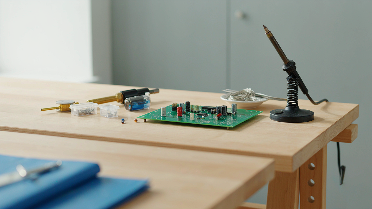
The Thermal Inertia Fallacy: Why Your Iron Isn’t “Hot Enough”
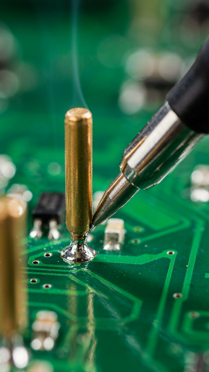
Temperature Settings Don’t Matter As Much As You Think
You want to believe a higher temperature setting solves your problems because it feels like control. It doesn’t. Thermodynamics doesn’t care about your dial. The real mechanism is thermal transfer rate, borrowed from heat engineering: the speed at which energy moves from the iron tip into the joint and board. A 400-degree tip transfers heat slower to a cold pad than a 450-degree tip, but only marginally if the contact time stays constant. Most people crank the temperature because they hold the iron on the joint too long, not because the baseline heat is insufficient.
The common advice says “use 350 to 400 degrees for most components.” That’s incomplete. What matters is whether the iron can reach the melting point of solder (around 190 degrees for lead-free, 183 degrees for lead-based) faster than the board can dissipate that heat into the surrounding copper and substrate. A properly sized tip at 380 degrees on a standard through-hole pad will do this in 3-5 seconds. Oversized pads, ground planes, or heavy copper traces demand a hotter iron or a bigger tip, not a behavioral change on your part.
Mass Transfers Heat More Efficiently Than Temperature
The real enemy is thermal inertia, and here’s the actual mechanism: a larger iron tip holds more thermal mass. When that mass contacts the joint, it delivers heat at a rate proportional to the temperature difference and the contact area, not the absolute temperature reading. A small, thin tip at 450 degrees can lose thermal energy faster than it delivers it to a large pad. A larger tip at 400 degrees wins because it has more stored energy to give. The board itself is the heat sink. You’re fighting its mass, not your iron’s number.
This is why desoldering large components fails. The legs have high thermal inertia. The pads connect to copper planes with even higher inertia. Your iron can’t dump enough joules into the system fast enough. The solution isn’t a higher temperature. It’s a bigger contact area, longer dwell time, or pre-heating the board. Use a chisel tip for wide pads, not a conical one. Hold it on the joint until the solder flows freely, not until your timer goes off. Thermal mass wins every desolder.
The Desoldering Iron’s Anatomy: Beyond A Pointy Bit
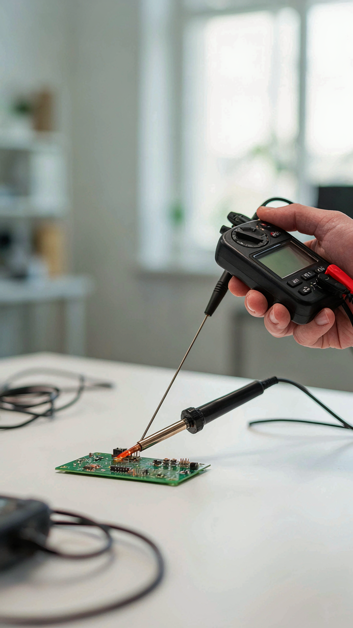
Tip Geometry For Optimal Thermal Bridge
You want the desoldering iron tip to look “professional” so you feel like you know what you’re doing. What actually matters: the tip must transfer heat to the joint, not just touch it. Thermal bridge is a physics term describing how heat flows from one mass to another. Your tip geometry determines the contact area and pressure distribution against the solder joint. A flat, beveled, or chisel-shaped tip creates more surface contact than a pointed cone. More contact means faster, more predictable heat transfer into the component leads and the board’s copper.
The common advice says “use a smaller tip for small components.” Wrong. A tip too small concentrates heat on too little area and can scorch pads or traces. A tip sized to match or slightly exceed the joint area spreads thermal load across the pad, reducing localized damage. The tip must also have enough mass to sustain heat delivery as it pulls energy from the joint. Copper tips conduct heat efficiently but oxidize fast. Plated tips resist oxidation longer and maintain consistent thermal delivery across multiple joints. Keep your tip wetted with fresh solder during work to improve thermal contact and speed up heat transfer.
Wattage To Thermal Mass Ratio
Wattage alone doesn’t determine desoldering speed or safety. The ratio of available power to the tip’s heat capacity does. A 40-watt iron with a small, thin tip delivers less sustained heat than a 40-watt iron with a thicker, heavier tip because the mass cools faster under load. Most entry-level irons rate at 25 to 40 watts, which works for through-hole and small surface-mount components if the tip retains enough thermal mass. Industrial setups run 60 to 100 watts specifically to maintain temperature when working with larger pads, thicker traces, or ground planes that sink heat rapidly.
The mistake: assuming higher wattage always means safer desoldering. A 100-watt iron with poor temperature control will overshoot and cook the board. Temperature control matters more than raw wattage. An iron set to 350 degrees Celsius with adequate thermal mass in the tip removes solder cleanly without lingering on the joint long enough to damage the substrate. Measure your actual iron’s tip temperature with a multimeter’s thermocouple function if you suspect it’s drifting. When the tip temperature drops more than 30 degrees under thermal load during a joint, your wattage-to-mass ratio is too low for your components.
The Flux First Protocol: Priming For A Clean Break
Why Fresh Flux Is Non Negotiable
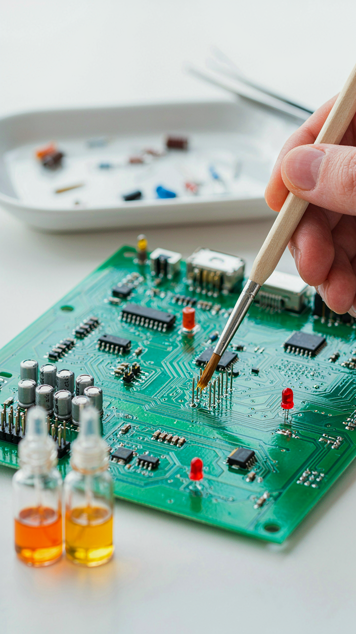
You want to look competent in front of someone who matters, so you rush the flux step. Don’t. Flux works through chemistry, not intention. Old flux oxidizes and loses its ability to reduce oxides on component leads and pads, making heat transfer spotty and pad lift likely. Fresh flux creates a protective atmosphere that prevents new oxidation while your iron melts the solder joint. The difference between old and new flux is the difference between a solvent that works and one that just sits there looking busy.

Rosin flux, water-soluble flux, and no-clean flux all degrade over time when exposed to air. The active compounds that break down oxide layers evaporate or oxidize themselves. Applying dead flux to a joint means your iron has to fight oxidation while melting solder, pulling heat away from the pad itself. The pad sees stress it shouldn’t. Buy new flux. Throw old flux away. This takes thirty seconds and saves boards.
Applying Heat With Solder Wire To Activate Flux
The mechanism here is thermal bridging. Your iron tip alone transfers heat slowly to a lead buried under solder. Adding fresh solder wire to the joint gives you a thermal conductor that touches both the iron and the lead simultaneously. The solder melts first, then conducts heat through the new joint to the component leg. Flux activates when it reaches temperature, not before. You’re not melting old solder to remove it yet. You’re priming the joint for the actual removal step that comes next.
Touch your iron tip to the joint, touch fresh solder wire to the iron tip just above the joint, let the solder flow around the lead and pad for two to three seconds, then remove the wire and iron together. The flux is now active and the entire joint sits at working temperature. This step takes discipline because it feels like you should start pulling the component immediately. You shouldn’t. The activated flux needs a few seconds to break down the oxides on the lead and pad surface. Skip this and you’ll shear pads on the next step.
The Capillary Action Gambit: When Solder Sucker Fails
Wicking Molten Metal Through Copper Braid
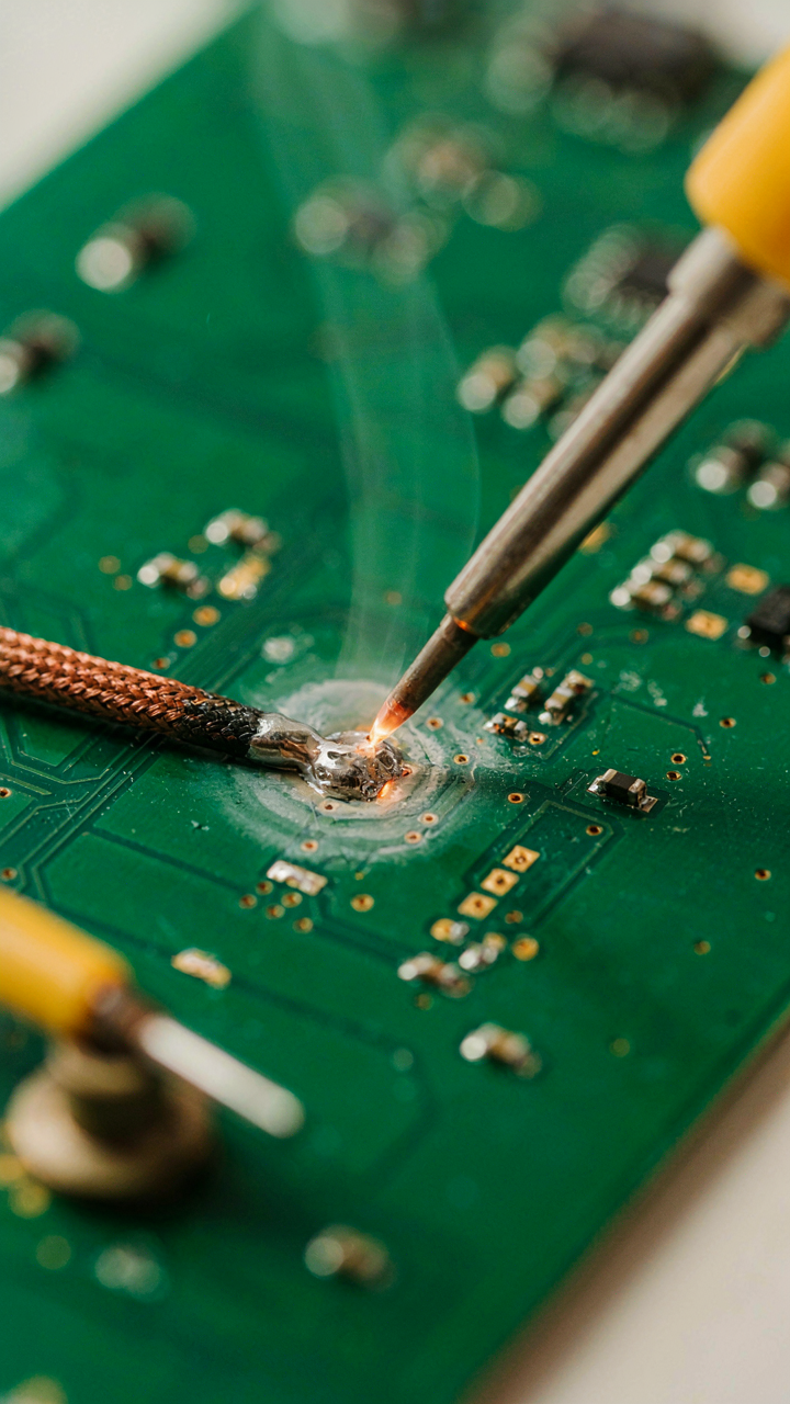
You want this section because you’ve already destroyed a board with a solder sucker and you’re looking for redemption. The physics here is straightforward: capillary action is the force that pulls liquid into narrow spaces against gravity. In desolder work, copper braid exploits this exact mechanism. The stranded copper fibers create thousands of microscopic channels. When you heat the braid against molten solder, surface tension drives the liquid metal upward into those channels faster than gravity can pull it down. This is why braid works when brute force fails.

The braid must make full contact with the solder joint. Air gaps kill capillary action instantly. Press the braid flat against the joint, not just touching it. The braid absorbs solder through wicking, not osmosis or suction. Once the braid saturates with solder, it stops working. Solder doesn’t wick into a fiber already full of solder. You discard saturated braid and use fresh material. This is the mechanism most people miss: they keep using the same braid, wondering why it stops pulling solder after three joints.
Heat Application Timing Breaks The Joint
Braid fails when you treat it like a passive tool instead of an active system. The real mistake is applying heat to the braid instead of the joint itself. Your iron should target the solder connection, not the copper braid. The braid sits on top, receiving radiant heat and contact heat from the molten solder, not from direct iron pressure. When you press a hot iron directly onto the braid, you superheat the copper and it conducts too much energy into the board traces. This is how you lift pads.
The timing protocol: heat the joint for two to four seconds before the braid touches it. This pre-melts the solder. Then apply the braid and iron simultaneously, with the iron still on the joint, not on the braid. The molten solder wicks into the fresh copper within five to eight seconds. Remove the iron first. Wait one second. Then remove the braid. If you reverse this sequence, the braid cools and bonds to the joint. You’ll tear the pad out trying to separate them.
Component Extraction: The Gentle Persuasion Method
Heat Distribution Across All Pins
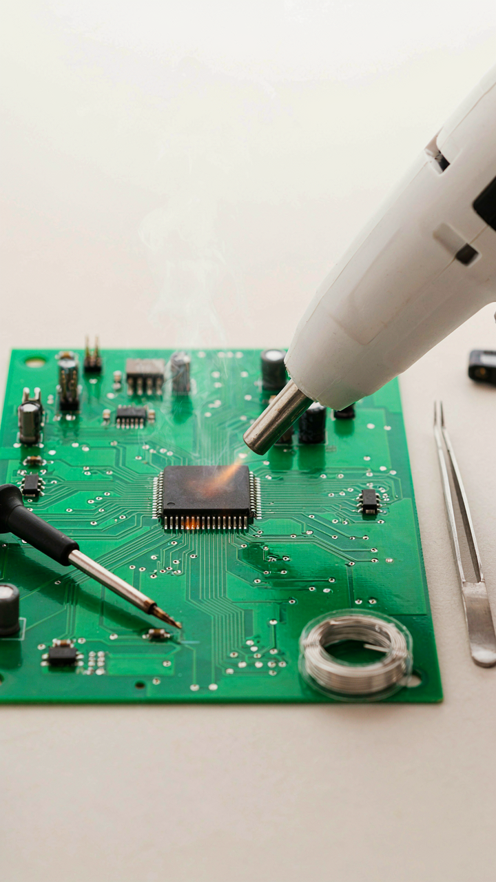
You want to avoid the sinking feeling of lifting a pad clean off the board, so you’re reading this. Here’s the mechanism: thermal stress concentrates at the coolest points. Borrowing from materials engineering, think of heat distribution like load balancing in a structure—uneven stress creates failure at weak points. A single iron tip on one pin creates a temperature gradient that pulls the solder joint apart unevenly, peeling copper traces from the substrate.

Use a heat gun or solder bath to warm the entire component to 180-200°C before touching individual pins with an iron. This preheating equalizes temperature across all pins simultaneously, making solder flow uniformly and reducing mechanical stress on each connection. Most advice skips this step. Don’t. The board stays cooler overall when you preheat because you’re no longer fighting cold solder that resists flow. Apply heat for 10-15 seconds across the component face, then use your iron to break individual joints in quick succession before the component cools.
Mechanical Advantage With Minimal Force
Stop trying to yank components straight up. Rocking them teaches a lesson that linear force won’t: side-to-side movement at low angles reduces the shear load on leads by distributing it along the bend radius instead of concentrating it at the base. A 15-degree rock in both directions while the solder is liquid creates micro-movements that let gravity and solder fluidity do the work for you.
Use a flat desoldering braid or solder sucker to clear solder from one side completely, then rock the component gently while heating the opposite side. The cleared side now has clearance and the lead can rotate slightly as you apply pressure. Never pull straight up. Never twist. The component exits when you’ve cleared enough pins that gravity assists extraction, not before. This typically means four to six fully cleared leads on a 16-pin DIP package before the part comes free.
The “Heat Sink As Firebreak” Strategy

Protecting Adjacent Components Through Thermal Isolation
You want to look like you know what you’re doing without actually risking the board. Here’s the mechanism: in military strategy, a firebreak is a cleared zone that stops wildfire spread. In desoldering, thermal mass works identically. Components near your target absorb heat meant for the joint, so they can fail before you even touch the solder. You need to block that heat migration before it happens, not after.

Aluminum foil and ceramic tiles redirect thermal energy away from vulnerable neighbors. Place them between your heat source and adjacent components during the desoldering process. The barrier doesn’t stop heat entirely—it slows its travel path and spreads energy over a wider area, reducing peak temperature at sensitive parts. This is the real reason nearby components fail: concentrated heat, not time.
Creating Barriers That Actually Work
Most advice tells you to “be careful with heat.” That’s useless. You need physical barriers that convert radiant and conductive heat into a problem somewhere else on the board. Thermal paste between your heat sink and the foil barrier increases contact efficiency, which counterintuitively makes isolation better—the heat transfers predictably into your barrier instead of scattering randomly into the board.
Copper shims work better than foil if you’re desoldering multiple components in sequence. They retain and dissipate heat more evenly, and you can position them to create a thermal wall. After positioning your barrier, hold it in place with ceramic tweezers or a small clamp, then apply your iron or hot air station. Remove the barrier only after the solder flows and you’ve lifted the component clear.
Post Desolder Cleanup: The Residue Reckoning
Why Clean Pads Matter For New Solder
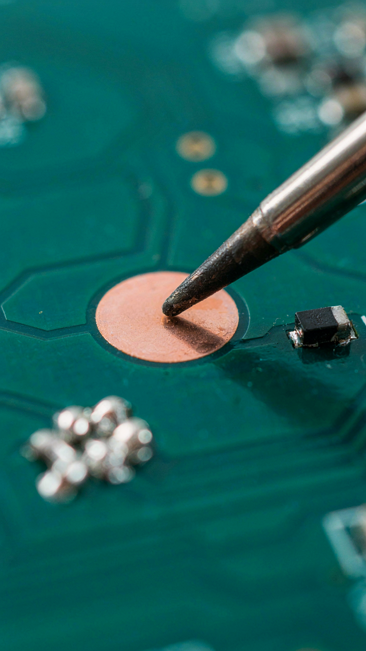
You care about this because a messy pad means your next joint fails and you look incompetent. Here’s the mechanism: flux residue and oxidation act as a thermal and electrical barrier between fresh solder and the pad. Solder wets copper. It does not wet burnt flux or oxide film. If residue remains, new solder sits on top like a ball on glass instead of flowing into molecular contact with the pad surface.

The pad’s surface energy determines solder flow. Contamination inverts that energy equation. Even microscopic residue blocks the capillary action solder needs to form a mechanical and electrical bond. This is why boards reworked without proper cleanup fail inspection or fail in the field. A clean pad accepts solder. A dirty pad rejects it.
Solvents And Methods That Actually Work
Most guidance says “use isopropyl alcohol and a brush.” That’s incomplete. The real problem is flux chemistry varies by type, and not all solvents break down all residues equally.
- Isopropyl Alcohol (IPA): Removes rosin flux and light oxidation effectively. Use 90% concentration or higher. Soak the area for 30 seconds, then brush directionally to lift debris off the pad.
- No-Clean Flux Residue: Requires stronger action than IPA alone. These residues are hygroscopic and acidic. Ultrasonic agitation in IPA for 2-3 minutes breaks the bond faster than manual brushing.
- Acetone: Dissolves rosin flux faster than IPA but attacks some board coatings and conformal coatings. Use only on exposed copper or when you’ve verified the coating tolerates it.
- Desoldering Wick Residue: After wick removal, oxidized copper remains. A brass wire brush or soft brass bristle brush removes this without gouging the pad. Work perpendicular to pad traces to avoid lifting copper laminate.
- Flux Pen And Solder Sucker Combo: Fresh flux applied to old residue lowers surface tension and helps suction remove molten debris. This is prevention, not cleanup, but prevents heavy residue buildup.
The mechanism is dissolution and mechanical agitation working together. Solvent penetrates the residue matrix. Agitation (brush, ultrasonic, or solder sucker action) breaks the mechanical bond between residue and copper. Wipe the area dry immediately after with lint-free cloth to prevent reoxidation. A clean pad accepts new solder on the first attempt.
Advanced Desoldering: Beyond The Iron
Hot Air Rework Station Precision Heat Delivery
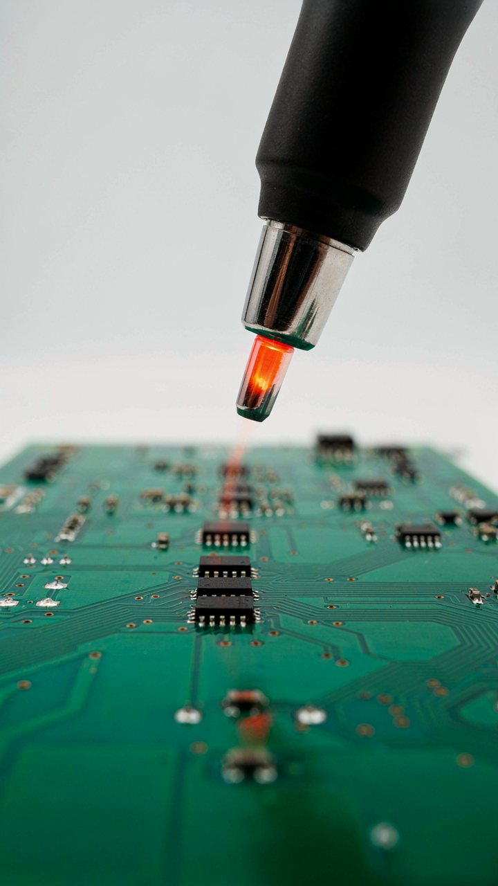
You want this section because you’re afraid of torching a board with an iron and looking incompetent. Here’s the mechanism: hot air stations control heat distribution across a component’s footprint instead of concentrating it at a single point. Traditional irons create thermal gradients that stress solder joints and traces. A rework station delivers uniform heat to the entire pad array simultaneously, reducing mechanical shock to the PCB.

Temperature control matters more than wattage. Most stations dial between 200 and 450 degrees Celsius with adjustable air flow. The nozzle size determines coverage area. Smaller nozzles target individual components. Larger nozzles heat entire regions. You preheat the board to 150 degrees Celsius first, then ramp the nozzle temperature gradually to avoid thermal shock. Solder reflows visibly when ready. Remove the nozzle and lift the component cleanly without jerking.
Specialized Tools For Multi Pin Components
Every advice column tells you to use flux and patience. That’s incomplete. BGA and QFP components demand mechanical assistance because solder paste under 100+ pins won’t reflow uniformly with air alone. Vacuum pickup tools, solder wick in staged widths, and desoldering braid designed for fine pitch work are non-negotiable.
Vacuum desoldering stations (not handheld pumps) pull molten solder directly from joints while heat is applied. This removes the reflow residue faster and prevents bridging when you lift the component. Solder wick absorbs excess molten solder before it re-hardens across multiple pins. Quality wick has consistent copper weave density and minimal voids. Stage your removal: heat the entire component to reflow temperature, use the vacuum tool on three corners, then lift diagonally to distribute stress evenly across the footprint.
The Real Obstacle Isn’t The Solder Joint; It’s Your Attachment To Outdated, Inefficient Methods
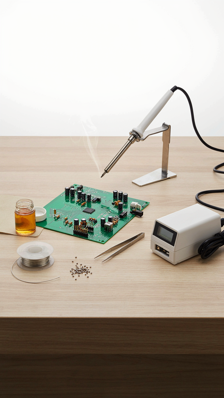
Most people desolder components the same way they learned it ten years ago. They waste time, destroy boards, and blame the tool instead of their approach. The shift happens when you stop treating desoldering like a problem to tolerate and start treating it like a skill worth mastering. Your only move today: pick one board you’ve been afraid to work on and commit to using heat properly instead of force. The best desoldering technique is the one that teaches you why you were doing it wrong in the first place.