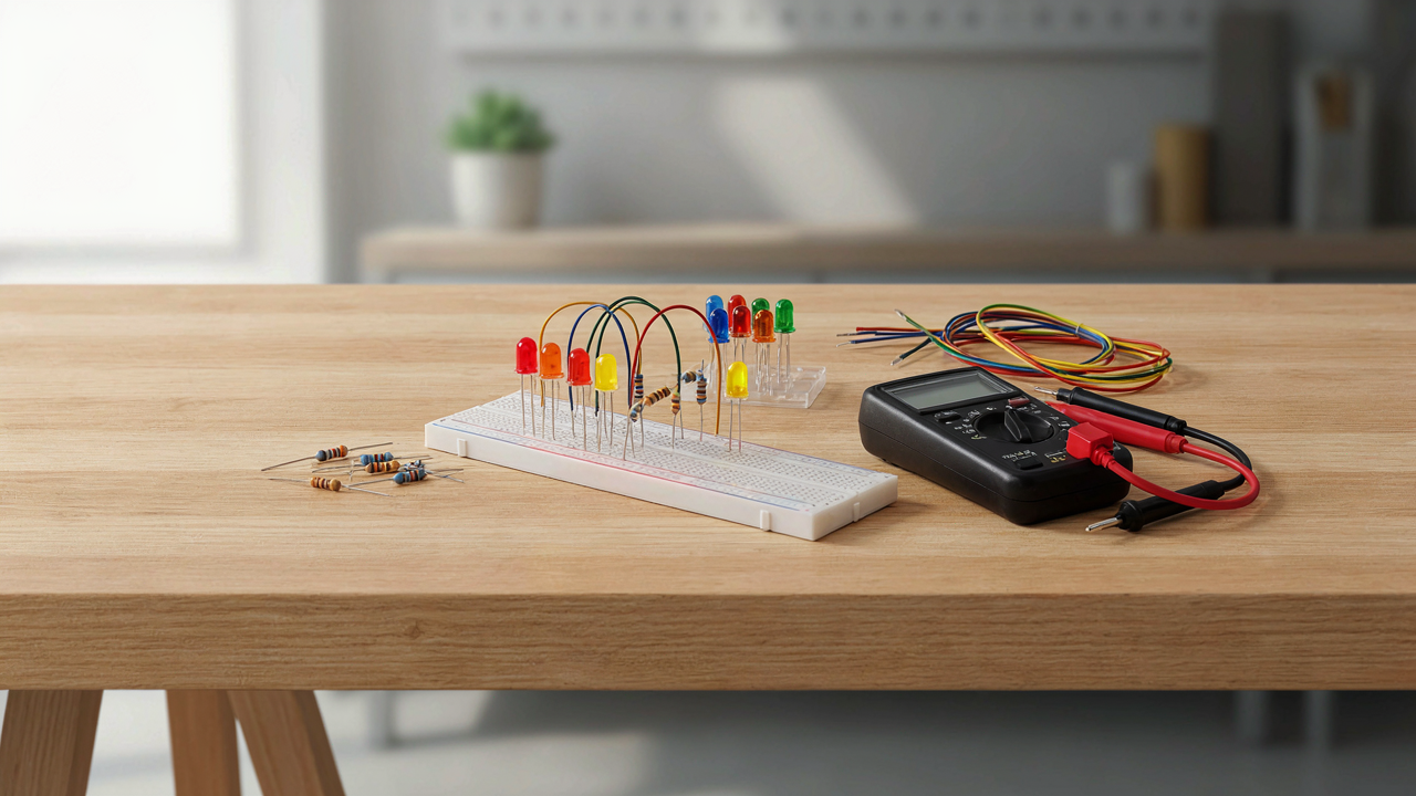
The Illusion Of Easy Breadboard Projects: Why Tutorials Fail You
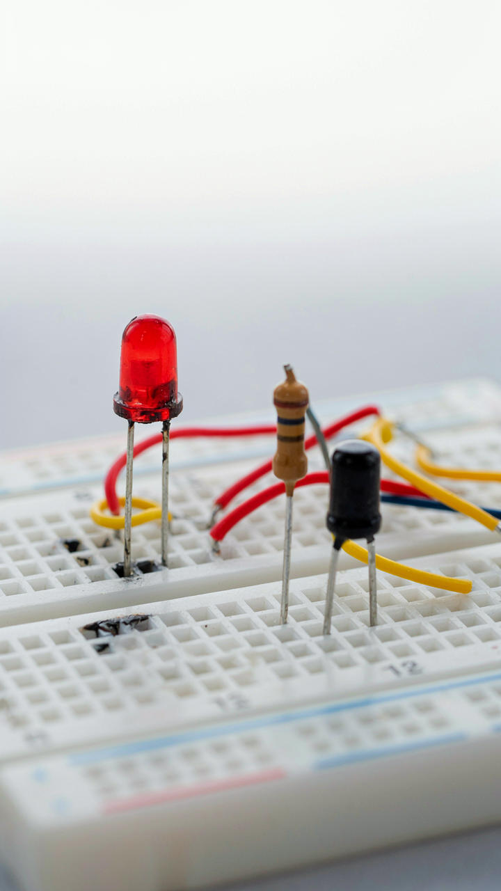
The Tutorial Trap
You’re drawn to breadboard projects because you want proof you can build something that works without admitting you’re starting from zero. Here’s what kills most beginners: tutorials show you the happy path, not how circuits actually fail. You follow steps, the LED lights up, and you think you’ve learned electronics. You haven’t. You’ve memorized a sequence.
Real learning requires understanding why each component does its job and what breaks when you deviate. A tutorial shows you a resistor in series with an LED. It never explains that the resistor limits current to protect the LED, or what happens if you remove it, or how to calculate the right value for a different voltage. You get surface compliance, not mechanism. That gap is where most beginners stall out after three projects.
Beyond Works Understanding Component Interaction And Failure Points
In systems thinking, you map inputs, processes, and outputs to understand how a system behaves. A breadboard circuit is a system. Most tutorials skip this entirely and treat components as black boxes that magically produce results. You need to see the interaction: a switch opens and closes a path, a resistor resists the flow of current, a capacitor stores charge over time. Each component changes the behavior of the others.
The real test isn’t whether your circuit works. It’s whether you can predict what happens when you change a value, swap a component, or move a wire. Build a simple LED circuit, then answer this: if I use a 470 ohm resistor instead of 220 ohm, what changes? If you don’t know, you’re not ready for the next project. You need to measure voltage across the resistor with a multimeter, calculate current using Ohm’s Law, and trace the path current takes through every component before power shuts down. That’s the protocol that builds real skill.
The Bare Bones Bread Board: Essential Gear, Zero Fluff

What You Actually Need To Start
You want permission to buy less because you’re afraid dropping money on gear you won’t use looks stupid. Here’s the mechanism: constraint forces learning. The fewer tools you own, the deeper you understand each one. Breadboarding borrowed the economics principle of scarcity—when supply is limited, demand for knowledge increases. You learn faster under pressure.
A breadboard itself, wire, a power source, and components. That’s the floor. Most beginners stock up on everything at once, then abandon half of it. The real play is starting with exactly what one project requires, then adding only what the next project demands.
- Solderless Breadboard (830 or 400 tie points): Start with 830 if you’re building anything beyond single LED circuits. The 400-point board runs out of space too fast and forces you to rebuild instead of troubleshoot.
- Solid Core Wire (22 AWG): Use this, not stranded. Solid core seats properly in breadboard holes and holds its shape. Stranded wire frays and creates loose connections that kill hours of debugging.
- Power Supply (5V USB or battery pack): Pick one and stick with it for your first five projects. Consistency eliminates variables. A basic USB power adapter works. Don’t buy a lab bench supply yet.
- Resistor Assortment (common values: 220 ohm, 1K, 10K): You need maybe ten resistors across three values to start. Buy them. Everything else is excess that sits in a drawer.
- LEDs and Basic Semiconductors: One pack of 5mm LEDs and one 555 timer IC. These cover 80 percent of beginner projects. Add components as specific projects demand them, not before.
Everything else you’ll buy is either a duplicate or a mistake. The breadboard industry counts on hoarding behavior. You’ll hear that you need “complete kits” with fifty components you’ll never touch. Ignore that. The real cost isn’t the money you spend upfront—it’s the decision fatigue from owning too many options.
Focus On Parts That Repeat Across Projects
Most advice says to build a component library. That’s incomplete. Building a library means you’ve already bought things. The real move is identifying which parts appear across multiple projects, then buying those first. Economics calls this inventory turnover. In breadboarding, it means your resistors and LEDs get used repeatedly instead of sitting idle.
Five projects share common parts: LEDs, resistors, pushbuttons, and 555 timers. Forty projects add transistors, capacitors, and shift registers. Start with the overlapping set. When you finish project two and see you’re using the same 220 ohm resistors again, you’ve validated that buy. When project three needs something new, you add it then. This approach cuts waste and keeps your attention on learning, not inventory management.
Deconstructing The Breadboard Layout: See Beyond The Holes
The Power Rails Are Not Optional
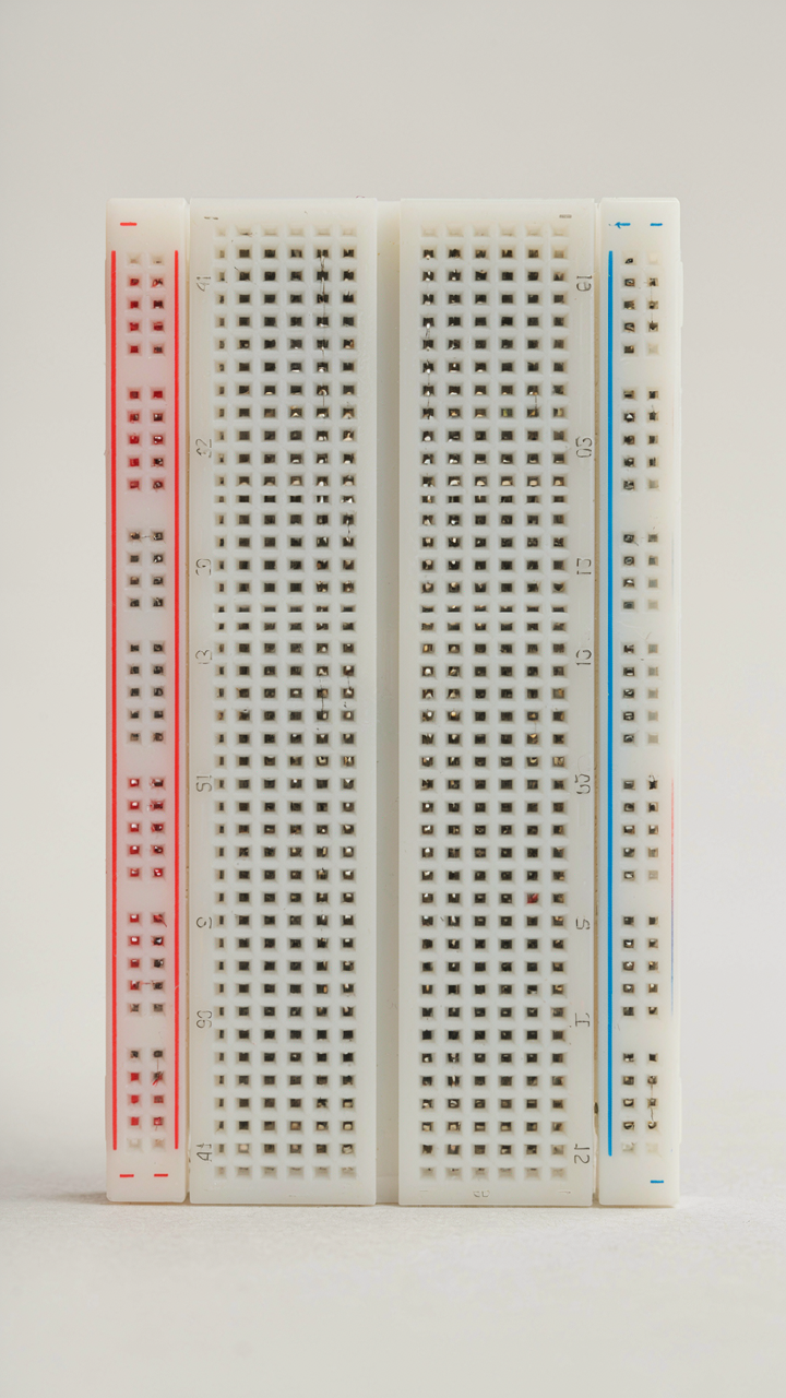
You want to skip learning this because it feels like invisible plumbing when you just want to blink an LED. Here’s the mechanism: a breadboard’s power rails run vertically along the edges, separate from the main grid. Every component needs voltage and ground to function. The rails distribute these two things to every row simultaneously, which is why they exist at all.

The red and blue lines printed on breadboards mark these rails, but the printing is just a map. Internally, each hole in a power rail connects horizontally to every other hole in that same rail. You plug power into one end, and voltage flows through the entire column. Ground works the same way. Most beginner mistakes happen because someone plugged power into the grid instead of the rail, starving their circuit of current before it even started.
Placement Strategy Beats Wiring Chaos
Treat breadboard layout like circuit topology in electrical engineering. In topology, the physical path doesn’t matter as much as the connections do, but on a breadboard, placement directly determines how many wires you’ll need and how readable your circuit becomes. Random plugging creates a rats nest that hides short circuits and makes troubleshooting impossible.
The real protocol: place your power rails first, then position components by function, not by whim. Put resistors near the component they’re protecting. Put capacitors near the chip they’re filtering. Keep signal paths short. When you wire intentionally, you see the actual circuit logic instead of playing maze-runner with jumpers. This isn’t aesthetic preference. Short paths mean fewer voltage drops and faster signal propagation. Long chaotic wiring introduces problems that don’t exist in your design.
The Power Flow Protocol: How To Power Breadboard Circuits Safely
Match Voltage To What You’re Running
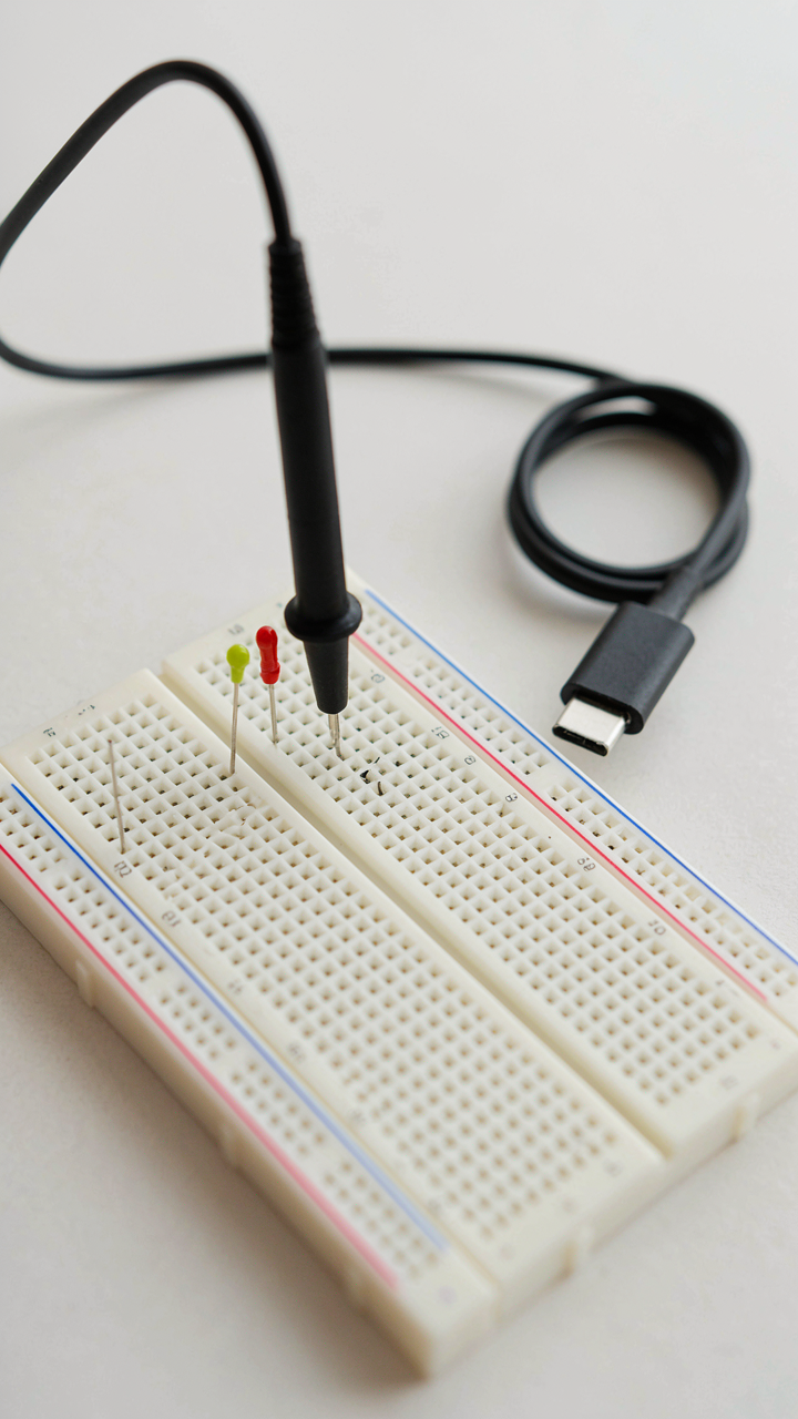
You want to avoid looking incompetent in front of whoever watches you build this. The real mechanism is simpler: voltage is the pressure pushing electrons through your circuit, and every component has a rated voltage it expects. Exceed it and the component fails. Stay below it and nothing works. Most beginner components run on 5V or 3.3V. Your power source must match, not approximate.

A 9V battery powering a 5V LED circuit doesn’t work like “close enough.” The extra 4V finds the path of least resistance, usually straight through your LED’s junction, cooking it in seconds. A USB cable outputs 5V. A standard AA battery outputs 1.5V. Know what your breadboard project actually needs before you plug anything in. Check the datasheet or the component’s markings. This step takes thirty seconds and prevents a wasted afternoon.
Set Current Limits Before Damage Happens
Current is what kills components, not voltage alone. Physics uses the term “resistance” as a force opposing flow; in breadboards, a resistor is your active brake pedal on current. Every component has a maximum current it can handle before internal heating destroys the semiconductor junction or burns through a wire trace.
The real advice most tutorials skip: add a current-limiting resistor inline with every component that draws current. An LED draws 20mA max. A 220-ohm resistor between your power and the LED brings that current down to safe levels. Without it, the full battery current floods the LED and it fails instantly. Calculate using Ohm’s Law: resistor value equals voltage divided by desired current. A 5V source with a 10mA target needs a 470-ohm resistor minimum. Measure twice, solder once.
Beyond The Electronic Circuit Diagram And Breadboard: Building From First Principles
Circuits As Adaptive Systems
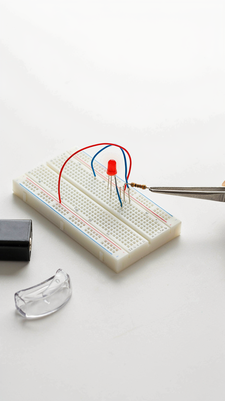
You want to feel smart by understanding something “deeper” than just following diagrams. The real mechanism is this: biology teaches us that living systems survive through feedback loops, and circuits operate on the same principle. Your LED circuit isn’t a static object. It’s a feedback system where voltage, resistance, and current constantly negotiate with each other. When you change one variable, the system recalibrates. Understanding this frame means you stop treating breadboards as instruction-following machines and start seeing them as networks with cause-and-effect relationships that expose themselves through testing.

The jump happens when you recognize that a resistor isn’t a passive obstacle. It’s a gatekeeper that protects other components by forcing the system into balance. Current wants to flow freely, but the resistor creates tension. That tension is what keeps an LED from burning out. Once you internalize this living-system perspective, you build with intention instead of rote compliance. You predict what happens before you wire it because you understand the negotiation happening inside your circuit, not just the rules written in a tutorial.
Design Through Iteration, Not Perfection
Common advice says breadboard projects teach you circuits. It doesn’t. They teach you something sharper: how to evolve a design toward robustness through repetition. Each time you test a configuration, you gather data about what breaks and why. That data compounds. You’re not optimizing for elegance on the first pass. You’re optimizing for survival through cycles of small failure.
Take a simple LED blink project. The first version works once, then fails under different power conditions or wiring mistakes. You rebuild. You notice the rebuilt version handles slight voltage drops better. You tighten tolerances on your resistor values. You add a capacitor you didn’t need before because testing revealed noise. Each iteration removes one fragility. After five cycles, you’ve built something that works not because you followed a pristine blueprint, but because you’ve eliminated specific failure modes through evidence. That’s how real engineers work.
Debugging The Mess: Real World Breadboard Projects Troubleshooting

Isolate The Problem, Not Your Ego
You want to feel like you know what’s wrong without actually tracing the fault. That’s the real reason troubleshooting feels hard. Here’s the mechanism: most beginners debug by changing random components, hoping one sticks. You need systematic isolation instead. Divide the circuit into segments. Test each segment independently. This is the military concept of “divide and conquer” applied to electrons. You isolate the faulty zone before you touch anything.
Start at power delivery. Verify voltage reaches the breadboard rails with a simple visual check of your connections first. Then methodically disconnect components in stages. If the circuit works after removing a section, the problem lives in that section. If it still fails, the fault is elsewhere. This approach cuts debugging time from hours to minutes because you’re eliminating working components, not guessing blindly.
Reading Voltage And Current Without Panic
A multimeter is not mysterious. It’s a tool that reads two things: voltage across a point and current flowing through a path. You already understand the mechanism. You need to know where to place the probes and what numbers matter. Most beginners skip this and wonder why their circuit stays broken.
- DC Voltage Setting: Red probe to test point, black probe to ground. Read the number. Compare it to your circuit schematic’s expected value. Deviation means a break or short upstream.
- Continuity Mode: Tests if current can flow between two points with no voltage applied. Beeping means connection exists. Silence means an open circuit or bad solder joint.
- Resistance Mode: Measures ohms. Power must be off. Use this to spot dead components like burned resistors or LED leads that snapped internally.
- Current Mode: Inline measurement only. Insert multimeter into the circuit path. Tells you if current flows at expected levels. Draws too much current? Component is likely shorted.
- Ground Reference: Always set your black probe to ground first. Every voltage reading is relative to ground. Floating probes give garbage data.
Start with voltage checks on power rails, then trace signal paths through your components. Write down what you find. Numbers don’t lie. Bad solder joints, reversed polarity, and disconnected wires show up immediately. Your multimeter is the fastest way from confusion to clarity because it removes guessing from the equation.
From “Easy Breadboard Projects” To Independent Creation

Build, Test, Refine In Loops
You want to skip the grunt work and jump straight to looking like you know what you’re doing. Here’s the actual mechanism: iteration destroys the gap between intention and result. You build something, it fails in specific ways, those failures tell you exactly what to change next. This is how learning compresses.

Start with a simple LED circuit. Power it. It works or it doesn’t. If it doesn’t, you probe the voltage at each point. You move a wire. You test again. Each loop takes five minutes. After three loops, you’ve internalized why current flows where it does. Skipping this cycle and watching videos instead leaves you helpless when your own circuit dies.
The common advice says “build projects to learn.” Wrong framing. You don’t learn from building. You learn from the collision between what you expected and what actually happened. Document that collision. Write down what you predicted would happen, what happened instead, and why. Do this ten times and you’ve built a mental model that transfers to circuits you’ve never seen.
The protocol: Build the circuit exactly as shown. Power it. Write down the observed behavior in one sentence. Change one component or connection. Power it again. Write the new behavior. Compare. Repeat until you understand the causal chain. Stop when you can predict the next failure before testing it.
Breaking Problems Into Working Pieces
Systems thinking comes from engineering, where you decompose a machine into subsystems that each solve one problem independently. A power supply subsystem. A signal generation subsystem. A detection subsystem. A breadboard works the same way, just at smaller scale.
Most beginners try to understand an entire audio amplifier circuit at once. You can’t. The circuit has forty components. Instead, isolate the voltage regulator section first. Build only that. Verify it stabilizes five volts. Now remove it as a black box. Build the amplifier section next, assuming clean five-volt input. Test in isolation. Finally, connect them. Each piece is testable alone.

This modular approach does something critical: it cuts your debugging time by eighty percent. When the amplifier doesn’t work, you already know the power supply is good. You search only the amplifier logic. You don’t chase phantom problems across both systems. When you can pull a module off the breadboard and it still makes electrical sense as a standalone unit, you’ve built something that scales.
The protocol: Identify the functional sections of your project before building anything. Power, signal input, processing, output. Build power first. Test with a meter. Add signal input next. Test each section in order. Never connect untested pieces to tested ones. Document the voltage and signal shape at each module boundary.
Your First Breadboard Electronics Project: Ditch The Blueprint

Build Without A Diagram
You want a diagram because you’re afraid of breaking something. That’s the real barrier. The mechanism is simple: diagrams create a false sense of safety. They don’t. What actually keeps your circuit safe is understanding voltage, current, and component ratings. A diagram just masks whether you know those things.
Start with the simplest possible circuit: a battery, a resistor, and an LED. Place the positive battery lead on the breadboard’s positive rail. Run a wire from that rail through a 220-ohm resistor into the LED’s longer leg. Connect the LED’s shorter leg back to the negative rail. That’s the entire design. You don’t need permission from a diagram to do this.
Learn By Destroying Things
Failure isn’t failure if you know what broke and why. The common advice says to “test everything” and “be careful.” That’s incomplete and lazy. What matters is systematic destruction: intentionally short circuits, reverse polarity, wrong resistor values. You’ll learn more from a dead LED than from ten working ones.

Burn out a resistor by removing it mid-circuit. Short two rails together and watch the voltage drop. Use the wrong resistor value and see how brightness changes. Each mistake teaches you the relationship between components faster than any tutorial. Document what happened, what you changed, and what the result was. Build the next circuit with one variable different. That’s the protocol.
The Real Obstacle Isn’t Complex Circuits; It’s Your Addiction To Hand-holding
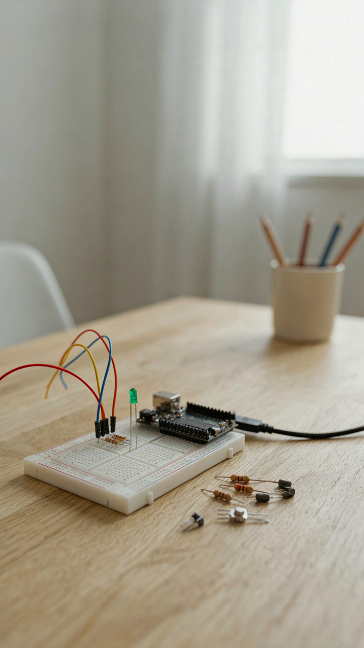
You don’t need another tutorial. You need to break the tutorial habit. Breadboard projects for beginners work because you fail fast and learn from actual mistakes, not sanitized videos. Stop watching and start building the LED circuit today. Plug in components. Watch it fail. Fix it yourself. That friction between confusion and clarity is where the real learning lives. You don’t become an engineer by consuming information. You become one by debugging your own broken circuits.