The Myth Of “Gentle Handling” For Vintage Radio Repair
Stop Waiting For Permission To Test
You’re afraid you’ll break something that’s already broken. That’s the real reason you’re reading this section. The mechanism at work here is psychological avoidance dressed up as caution. Vintage radios fail because components degrade over decades. A capacitor that’s been leaking since 1968 won’t suddenly recover because you handle it delicately. Assessment requires stress testing, not reverent observation from across the room.
Most restoration guides tell you to visually inspect first and proceed gently. This is incomplete advice that wastes your time. You need to apply electrical load to components to reveal their actual state. A capacitor might look fine but measure at half its rated capacity. A transformer might appear intact but have open windings that only show up under resistance testing. Gentle handling masks problems rather than solving them.
Open The Radio Before You Understand It
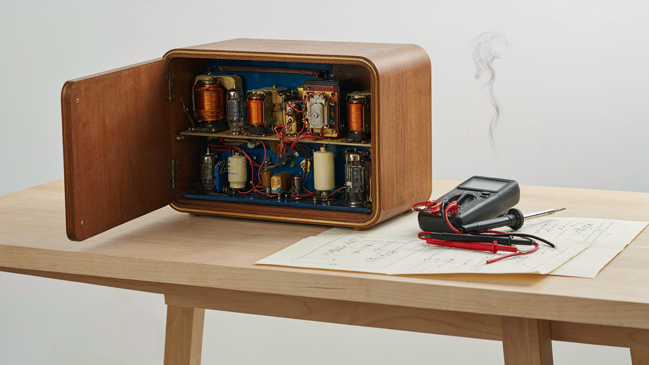
You cannot diagnose a vintage radio without dismantling it. The metal chassis and wooden cabinet create a black box that prevents real assessment. Tubes sit in sockets, capacitors hide their age, and resistor color bands fade behind accumulated dust. Radio design from the 1930s through 1950s packed components tightly, meaning visual inspection from the exterior reveals almost nothing.
The standard warning about “being careful with old solder and fragile wiring” addresses a real concern but inverts the priority. Old solder is brittle and connections fail easily, which is why you need to locate and document every weak point now rather than later. Use a desoldering pump or wick to remove old solder cleanly. Take photographs of the board layout before you touch anything. This isn’t gentleness. This is systematic documentation that enables confident repair.
Beyond Cleaning: The Deconstruction Doctrine For Old Radios

Reading The Circuit Before You Touch Anything
You want to feel competent before you start, which is why you’re tempted to skip the schematic. Don’t. The schematic is your operating manual for understanding what actually fails and why. Military electronics doctrine calls this “systems mapping”—you identify dependencies before you engage the target. A vintage radio’s circuit is the same: tube stages feed into transformers, which feed into capacitors, which feed into speakers. You cannot see these relationships by looking at the chassis.

Schematics exist for most radios manufactured after 1930. Find the manufacturer, model number, and production year, then search tube radio databases or archived documentation. The schematic shows you the signal path from antenna to speaker. Trace it. Write down every component type: tubes, resistors, capacitors, transformers, chokes. Note which components are in series and which are parallel. This single act—reading, not touching—eliminates 90 percent of the guessing that kills radios during restoration.
Separating Real Damage From Surface Decay
Most people mistake cosmetic for critical and waste months on irrelevant problems. A dented speaker grille matters zero. A leaking electrolytic capacitor matters everything. The difference is whether the component controls signal flow or just looks aged. Tubes that glow but produce no output are critical failures. Discolored resistor bodies are cosmetic. You need one sorting rule: if the radio powered on yesterday and works today despite the defect, it’s cosmetic. If the radio won’t power on or produces no sound, the defect is critical.
Start with the power supply and output stage first. These are failure points with cascading effects. A failed power transformer creates no high voltage, so nothing downstream runs. A failed output tube produces no speaker signal. A failed coupling capacitor blocks that signal. Work backward from these bottlenecks to identify what you actually need to fix versus what you can safely leave alone for now. This sequencing prevents you from replacing components that aren’t broken and keeps you focused on restoration, not renovation.
The Capacitor Contradiction: Ignoring “Originality” In Restoring Old Radios
When Original Parts Become Liabilities
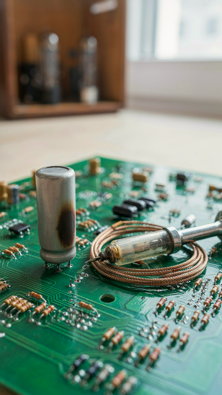
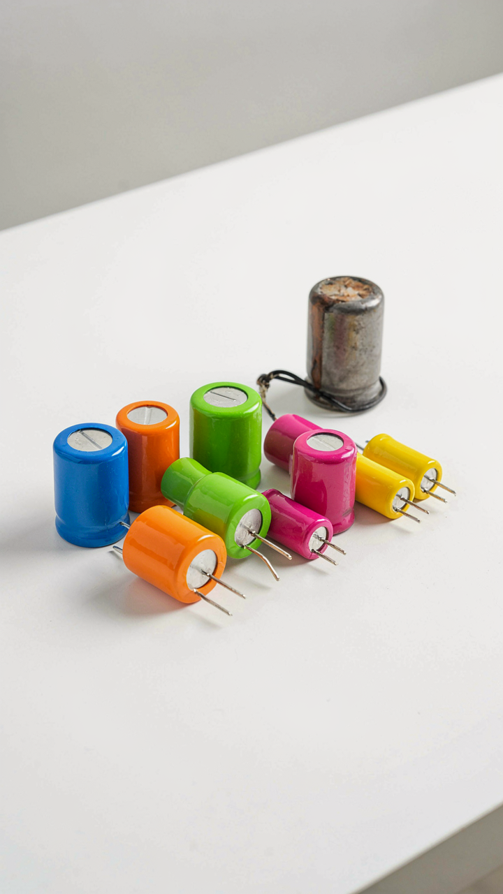
You want to keep it “authentic” because swapping parts feels like cheating, like you’re not really restoring anything. Here’s the mechanism: old capacitors don’t degrade gracefully. They fail catastrophically. Paper and wax dielectrics absorb moisture over decades. Electrolytic capacitors dry out. When voltage crosses the threshold, they don’t just stop working—they short, burn traces, damage transformers, and occasionally catch fire. Originality means nothing if the radio destroys itself on the bench.

The engineering principle here is entropy, borrowed from thermodynamics: a system naturally moves toward disorder over time. In a 1950s radio, capacitors are the entropy accelerators. Their degradation isn’t linear. It’s hidden until it isn’t. You’ll power on a “restored” original radio, smell burning phenolic resin, and realize you built a fire hazard, not a collector’s piece. The decision to replace capacitors isn’t sentimental. It’s structural.
Modern Replacements Work Better Than Originals Ever Did
The common advice says modern film capacitors might sound “different” or “worse” than vintage types. This is incomplete thinking. Modern film capacitors have tighter tolerances, lower equivalent series resistance, and superior temperature stability. They don’t absorb moisture. They don’t degrade predictably into failure. A 1960s radio with period-correct capacitors was already compromised by manufacturing variance and environmental stress the moment it left the factory floor. You’re not downgrading to a modern part. You’re upgrading to what the designer actually intended.
Replacement strategy is straightforward: identify every capacitor in the signal path and power supply. Check the schematic for ratings. Order modern film capacitors or quality electrolytics that match voltage and capacitance values. Mount them physically near original locations to avoid rewiring the chassis. The radio will sound accurate because the circuit topology hasn’t changed—only the reliability of the components handling the signal has improved. This is the only path that lets the radio run for decades without becoming a repair loop.
The Signal To Noise Protocol: Diagnosing Silent Antique Radio Repair Guide

Where The Hum Actually Lives
You want to know why your radio sounds like it’s trapped inside a power transformer. Most guides tell you to “check your grounds” and move on. That’s incomplete. Hum and static aren’t problems to tolerate—they’re diagnostics. They tell you exactly where the signal path is broken or contaminated.

Start by isolating the source mechanically. Turn the radio on with no antenna connected. If hum disappears, your problem is external interference or antenna design, not internal. If hum remains, you’ve narrowed the failure to the power supply, audio stage, or grounding scheme. Mute the volume. Tap the transformer, capacitors, and resistors with a wooden stick. Movement in hum intensity pinpoints the culprit. This isn’t guessing. This is systematic elimination.
Tracing Current Like It’s A Map
Think of the audio path as a circuit delivering signal strength from input to speaker, the way logistics systems move resources from source to destination. Every junction is either a node or a leak. Most restorers check components in isolation. Wrong approach. You need to follow the signal’s actual journey under load.
Grab a multimeter set to AC voltage. Start at the antenna input. Measure voltage at each stage: detector, first audio amplifier, output transformer, speaker connection. Voltage should increase predictably at each gain stage. If voltage drops unexpectedly between two points, the component between them is consuming power without amplifying it. That’s your failure. Alternatively, use an audio signal tracer—a tool that lets you listen for signal presence at any point in the chain. Feed a small test signal into the antenna input and follow it downstream. When the signal dies, you’ve found the break.
Power Supply Paradox: Stability Over “Period Correct” Aesthetics
When Unregulated Voltage Kills Your Radio
You want the radio to look original because you think that proves you did the work right. The real problem is that original power supplies were engineered for planned obsolescence, not survival. Unregulated voltage swings wildly based on line voltage and load changes, hammering transformers, filter capacitors, and output tubes into early failure. This is basic electrical engineering: voltage regulation is a stabilization problem, identical to cruise control in a car maintaining speed despite road grade changes. Without it, your radio’s lifespan shrinks by years.

Original designs used simple rectifier tubes feeding LC filters that merely smoothed ripple without controlling voltage. When AC mains drift or load increases, the DC output voltage climbs or sags unpredictably. Tubes run hotter than designed. Electrolytic capacitors age faster under stress. The radio might function for a weekend, then the output transformer saturates and the audio cuts to a whisper. Stability over aesthetics is not a compromise—it’s the difference between a radio that works and a radio that fails.
Build For The Radio’s Actual Future
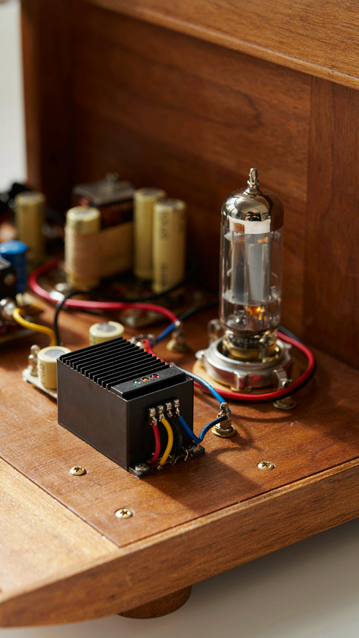
Replacing original components with modern equivalents is the correct move, not a betrayal of history. A modern solid-state power supply with voltage regulation costs under 50 dollars and keeps output voltage constant within 2 percent regardless of line voltage or speaker load. Tube radios were designed in eras when replacement tubes cost pennies and radios lasted two to four years before disposal. Your radio will outlive you if the power supply doesn’t stress it.
The mechanism is simple: regulated supplies use feedback circuits to sense output voltage and adjust the transformer tap or series resistance in real time. This prevents overvoltage stress on old components that can’t handle it anymore. Swap the original power transformer for a modern regulated unit with the same secondary voltage rating, keep the tube rectifier if you want the aesthetic, and wire the regulator module in series with the filter network. Your radio stops being a fire hazard and actually reaches ten years of reliable use instead of two.
Chassis As Foundation: The Structural Integrity Blueprint For Vintage Radio Restoration Guide

When Steel Becomes A Liability
You want to skip the chassis work because visible repairs feel invisible to performance. That’s denial masquerading as efficiency. The chassis is load-bearing architecture. Rust and metal fatigue operate like structural failure in buildings: stress concentrates at weakened points until the system fails suddenly, not gradually. A corroded mounting point doesn’t announce itself during normal operation. It fails when you power the unit on, when vibration resumes, when thermal expansion cycles resume after decades of dormancy.

Surface rust requires removal before reassembly because it accelerates under the conditions radios face: heat cycling, component vibration, moisture trapped by enclosures. Use a wire brush or fine steel wool to expose bare metal. Don’t sand aggressively or you remove material that controls tolerances. After rust removal, apply a thin coat of light machine oil or rust preventative like Cosmoline to exposed metal. This is not cosmetic. It stops the degradation loop that compounds through the restoration process and sabotages your work months later.
Reinforcing Points That Bear Load
Vintage radio construction used stamped steel and aluminum in ways that assume the chassis never moves again after assembly in 1938 or 1952. This assumption is wrong. You will handle it. You will move it. Mounting feet corrode and weaken. Tube socket mounting points flex under the weight of heavy transformers. Solder joints on the chassis itself can crack from thermal stress and mechanical shock.
Inspect all mounting points before full assembly. Look for cracks in welds or solder around tube socket bosses and transformer mounts. If cracks exist, the chassis requires reinforcement: solder a backing plate on the reverse side or install a small brace across the stress point. Check that all feet make contact with a flat surface. Replace missing rubber feet because bare metal feet transmit vibration directly to internal components and accelerate component failure. These steps take one hour and prevent complete reassembly failures.
Tube Test Treachery: What Your Tester Isn’t Telling You About Restoring Antique Radios Guide
The Meter Lies Under Load
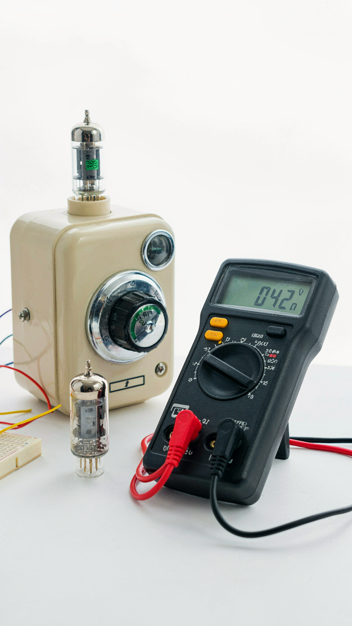
You want the reassurance that your tubes are good so you don’t waste a weekend pulling the wrong one. Here’s what kills that fantasy: a tube tester measures emission in isolation, which tells you almost nothing about how that tube performs when current actually flows through a radio circuit. Think of it like aeronautics—a wind tunnel measures drag coefficient, but that number means zero until you account for weight, thrust, and fuel burn in actual flight. Your tube tester operates in a vacuum-like state. It fires electrons at a cold cathode and counts how many make the jump. A dead tube fails this test. But a weak tube? It passes, because the tester uses minimal load current. Your radio’s output transformer demands ten times that.

The mechanism is simple: emission testing versus load testing measure different things. A tube can emit enough electrons to pass a tester yet fail under the voltage and current demands of a working receiver. The tester validates the cathode’s ability to produce electrons. It does not validate whether the tube maintains proper amplification when grid voltage swings, plate voltage climbs, and screen current spikes during modulation peaks. You need both checks. A tube that passes emission but fails under load will produce weak audio, distortion, or intermittent reception. Most hobbyists never discover this gap because they assume a passing tester result means the tube is restored to factory spec. It does not.
Performance Kills The Specification Sheet
Forget what the datasheet promises for a restored vintage radio. You’re not manufacturing tubes in a factory. You’re running a sixty or seventy year old component that has already lost internal vacuum integrity, cathode coating, and structural rigidity. The published specs assume new construction and perfect operating conditions. Your radio sits in a basement, pulls from a wall outlet that fluctuates, and demands performance under real thermal cycling. A tube rated for five hundred hours of life at nominal conditions has already burned through four thousand hours in service. The residual cathode material still emits electrons, but inconsistently.
Real-world performance testing means operating the radio at full power for thirty minutes, checking tube temperature with your hand, listening for distortion, and measuring plate voltage under signal load. If the audio stays clean, the tube holds its bias point, and nothing runs hot, the tube works. The datasheet spec becomes irrelevant. Your only standard is whether the radio functions reliably in your hands, not whether it matches lab conditions from 1952. Build a test protocol: run the radio on a signal generator at standard broadcast frequencies, measure DC plate voltage and grid voltage under modulation, then compare those readings across a full restoration cycle. That comparison tells you if a tube replacement actually improved performance or just changed the tester’s pass rate.
The Soldering Iron Manifesto: Precision, Not Patience, In Vintage Radio

Heat And Contact Time: The Real Variables
You want to believe the iron temperature matters more than it does because mastering one number feels like control. It doesn’t. The actual mechanism is thermal transfer: how fast heat moves from iron to joint depends on contact surface area, iron mass, and time in contact. Vintage radio work demands 350 to 400 degrees Celsius. Below that, solder won’t flow into the joint cleanly. Above it, component leads oxidize and the board traces lift. Temperature is the container, not the lever.

Dwell time is where precision lives. Three to five seconds of consistent contact melts solder evenly and lets heat soak into the component lead and pad simultaneously. Remove the iron too fast and the solder cools unevenly, creating a cold joint that fails silently months later. Remove it too slowly and you cook the component. The tell is solder flow: when it moves freely around the joint, remove the iron immediately. Chasing flow by hovering longer guarantees failure.
Flux: The Mechanism You’re Missing
Most hobbyists treat flux like a safety net. They load it on and hope oxidation doesn’t ruin the joint. That’s backwards. Flux is an active chemical agent that reduces metal oxides in real time, not a preventative blanket. In metallurgy terms, flux acts as a reducing agent, much like how a military supply line maintains operational capability. Without it, solder cannot bond to oxidized copper.
- Rosin flux (RMA): Works well for vintage radio work. Leaves mild residue that doesn’t require cleanup on most boards. Standard choice for hobbyists because it balances activity and safety.
- No-clean flux: Higher activity than rosin. Leaves almost no residue. More expensive but ideal if you’re worried about board longevity after restoration.
- Acid flux (NOT recommended for electronics): Corrosive and damages components. Only use on mechanical connections outside of radio circuits. Never touch tube pins or transformers with this.
- Flux application timing: Apply to both the pad and the component lead before heat. Reapply mid-joint if solder isn’t flowing after three seconds. Flux exhausts as temperature rises.
- Flux quantity: Use just enough to coat the joint area. Excess flux creates a barrier that traps heat and slows flow. A small dab beats a puddle.
Apply flux directly to the joint before the iron touches it. The moment heat arrives, flux activates and clears oxidation. Use it strategically, not defensively. Too much flux cools the joint and slows thermal transfer. Too little and oxidation wins. The iron removes the solder from the joint when flux has done its work correctly.
Calibration As Command: Taming The Frequencies In Antique Radio

Aligning IF Transformers For Peak Reception
You want this working because a dead radio feels like failure, and failure means you wasted your time. The mechanism is simple: intermediate frequency transformers sit between the detector and the amplifier stages, and they need to resonate at exactly the same frequency your radio’s designer specified. If they’re off, signal strength collapses and selectivity dies. Most hobbyists skip this step or guess at it. Don’t.

The IF frequency for AM radios is standardized at 455 kilohertz. This isn’t arbitrary. Early manufacturers locked onto this standard because it provided a clean band between broadcast frequencies and didn’t interfere with other circuits. You’ll find two variable capacitors inside each IF transformer can—one for coarse tuning, one for fine tuning. Your job is to peak both of them at 455 kHz using a signal generator and an output meter. Peak means maximum amplitude on the meter. Adjust slowly. One quarter turn changes the reading.
The Final Critical Adjustments For Clarity
Most guides tell you to “tune the dial and listen.” That’s incomplete. After IF alignment, you calibrate the oscillator coil and the antenna coil to ensure the dial markings match actual frequencies. The oscillator must track with the tuning capacitor across the entire band. If it drifts, stations won’t land where the dial says they should. This tracking error compounds across the band and makes the radio unusable despite good IF alignment.
Use your signal generator set to a known broadcast frequency—1000 kHz works well as a midpoint reference. Tune the radio dial to that frequency and adjust the oscillator trimmer until maximum signal reaches your meter. Check calibration at the low end (around 550 kHz) and high end (around 1600 kHz) of the band. Small adjustments to the antenna trimmer improve sensitivity at the high end without sacrificing low-end performance. Once locked in, the radio holds alignment for years.
The Long Term Play: Maintenance Beyond The Initial Vintage Radio Repair

Stop Waiting For Failure To Find You
You’re reading this because you’ve convinced yourself that once a radio works, you’re done. You’re not. The real fear underneath is that you’ll invest time into restoration only to watch it decay in real time, proving the whole thing pointless. That’s not how this works. Think of component degradation like corrosion in metallurgy: it doesn’t accelerate linearly. It sits dormant, then compounds fast once it starts. Your job is disrupting that curve before the inflection point.
Electrolytic capacitors dry out. That’s not a maybe. The electrolyte inside them evaporates, especially in radios stored in basements or garages where temperature swings and humidity levels aren’t controlled. You can’t stop this, but you can slow it drastically. Keep your radio in a stable environment between 50 and 70 degrees Fahrenheit with relative humidity between 30 and 50 percent. Avoid direct sunlight. Store it in a cabinet or box lined with acid-free paper. Check it every six months by powering it on briefly and listening for the hum to stabilize normally. If the sound takes longer to warm up or drifts in volume, capacitor failure is advancing.
When The Radio Tells You To Listen
Most hobbyists ignore early warning signs because they don’t know what they mean. Slight hum that wasn’t there before. A channel that drifts more than it used to. Volume that cuts out momentarily then comes back. These aren’t quirks. They’re diagnostic data. Your radio is telling you exactly which subsystem is failing before it fails completely.
Set a calendar reminder every twelve months to power the radio through a full cycle: all bands, all volume levels, a full hour minimum. Document what you hear. Keep a simple log with the date, any changes in tone, any channels that sound weaker, any hum patterns. Compare this log quarter to quarter. The moment you detect a shift from your baseline, you’ve caught the failure in progress. That’s when you pull the schematic, identify the suspect component, and replace it before the whole circuit collapses. Preventive maintenance isn’t constant fussing. It’s systematic observation.
The True Obstacle Isn’t The Faulty Capacitor, But Your Fear Of Irreversible Change

You don’t need permission to touch that radio. You don’t need certainty before you start. You need to accept that breaking something already broken teaches you more than reading about it ever will. Pick the cheapest broken radio you can find today. Plug in your soldering iron. The only irreversible change here is the one you avoid making.