
The Myth Of “Simple”: Why Your LED Isn’t Just “On”
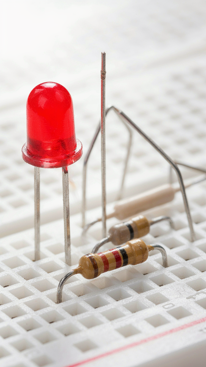
The Resistor’s Hidden Battle With Excess Voltage
You want to believe an LED circuit is straightforward because admitting it’s not means you’ve wasted time pretending to understand it. Here’s the mechanism nobody states plainly: a resistor doesn’t “limit” current like some friendly gatekeeper. It burns off excess voltage as heat. Borrow the physics term: voltage drop. The resistor converts electrical potential energy into thermal energy so your LED doesn’t self-destruct in microseconds.
Without a resistor, your power source shoves all its voltage through the LED’s junction at once. The LED has a forward voltage requirement, usually 2 volts for red, around 3.2 for blue. Feed it 5 volts raw and the excess 2 to 3 volts crash through the diode junction, spiking current to lethal levels. The resistor sits in series and claims that excess voltage before it reaches the LED. Calculate it: subtract LED forward voltage from your supply voltage, divide by desired current in amps, and you have your resistor value in ohms. That’s not theory. That’s your protection protocol.
The Diode’s One Way Gate: Electricity’s True Path
An LED is a diode with a directional current requirement that most guides bury in passing, and it costs you burned components when you wire it backwards. Think of this in semiconductor physics terms: a diode creates a depletion region at its junction that only conducts current in one direction. The positive lead (anode) must connect to positive voltage. The negative lead (cathode) must connect to negative or ground. Wire it reversed and nothing happens except the LED stays dark and heat builds inside.
Current flows from positive to negative, always. The LED’s cathode is the shorter lead and usually marked with a flat edge on the plastic casing. Strip that flat edge with your fingernail if you can’t see it clearly. Connect cathode to ground or negative rail, anode to the resistor, resistor to positive voltage. This is the only sequence that works. Build that habit and you stop troubleshooting why circuits that look correct stay dead.
Beyond Wires: The Unseen Force Driving Every Led Circuit
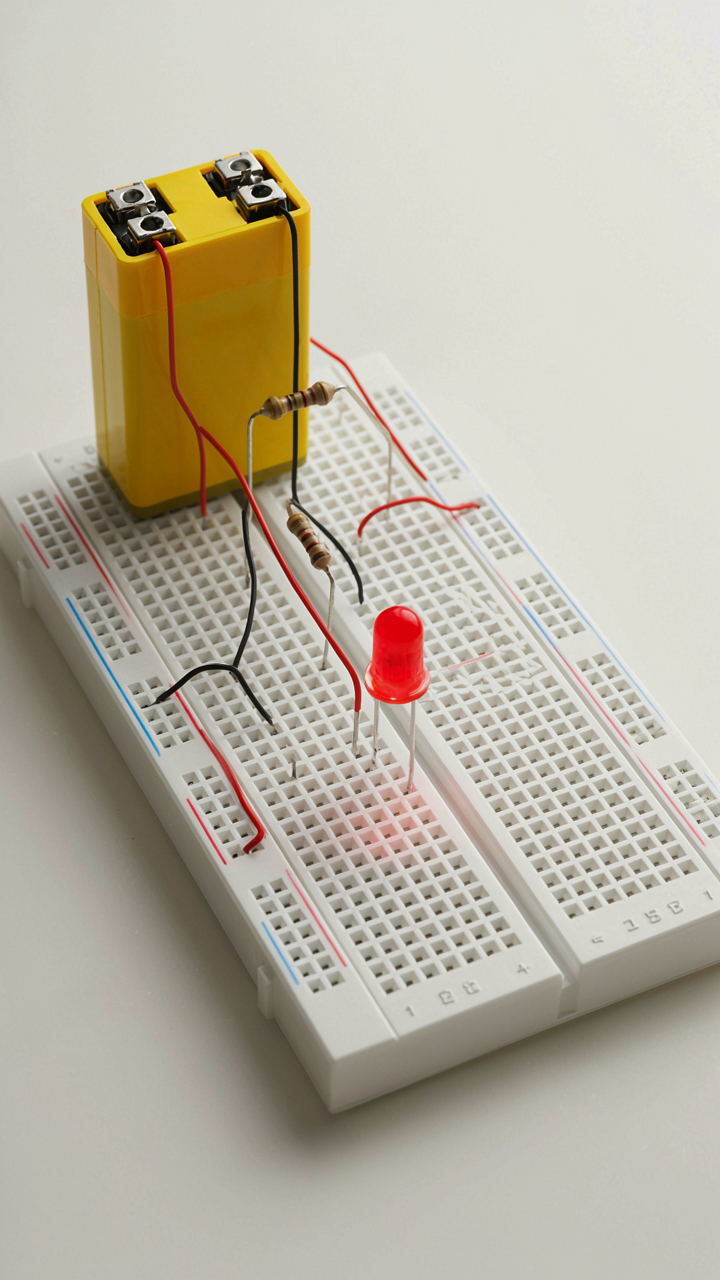
Voltage Potential: Electrical Pressure In Action
You want to understand this because you’re tired of being the person who nods along when someone mentions voltage without actually grasping what moves electricity at all. Voltage is pressure. In physics, we call this potential difference: the gap between two points that forces charge to move. Think of it like water pressure behind a dam. The higher the pressure, the more force pushes the water through. A 9-volt battery creates nine volts of pressure between its terminals. That pressure is what actually drives electrons through your LED circuit. Without it, nothing happens.

The voltage drop across your LED determines how bright it glows. A red LED typically needs about 1.7 to 2 volts to turn on. If you feed it 9 volts directly, you burn it out. This is why resistors exist: they consume the extra voltage and protect the LED. The resistor doesn’t block current. It converts unwanted voltage into heat. Your job is calculating the right resistor value so the LED gets exactly what it needs while the resistor absorbs the rest.
Current Flow: The Actual Movement Of Charge
Most people describe current as “electricity flowing through a wire,” which is lazy and backwards. Current is the measurable rate at which charge actually moves. Measured in amperes, one amp means one coulomb of charge passes through a point per second. An LED draws current because the voltage pushes electrons through it. That’s the real sequence: voltage creates pressure, pressure moves electrons, moving electrons become current. A typical red LED draws around 20 milliamps at rated brightness. A 9-volt battery supplying 20 milliamps to an LED without a resistor would dump all 9 volts through that LED and destroy it instantly.
The resistor limits current by increasing resistance, which forces voltage to drop across it instead of the LED. This is the mechanism everyone should state plainly but doesn’t: you size your resistor to limit current to a safe level for your LED. If your LED needs 2 volts at 20 milliamps, and you’re using a 9-volt battery, the resistor must drop 7 volts while allowing exactly 20 milliamps through. Use Ohm’s Law: R equals voltage divided by current. 7 volts divided by 0.02 amps equals 350 ohms. Pick the nearest standard resistor value and build the circuit.
The Feedback Loop Protocol: Mastering Your Led Flasher Circuit
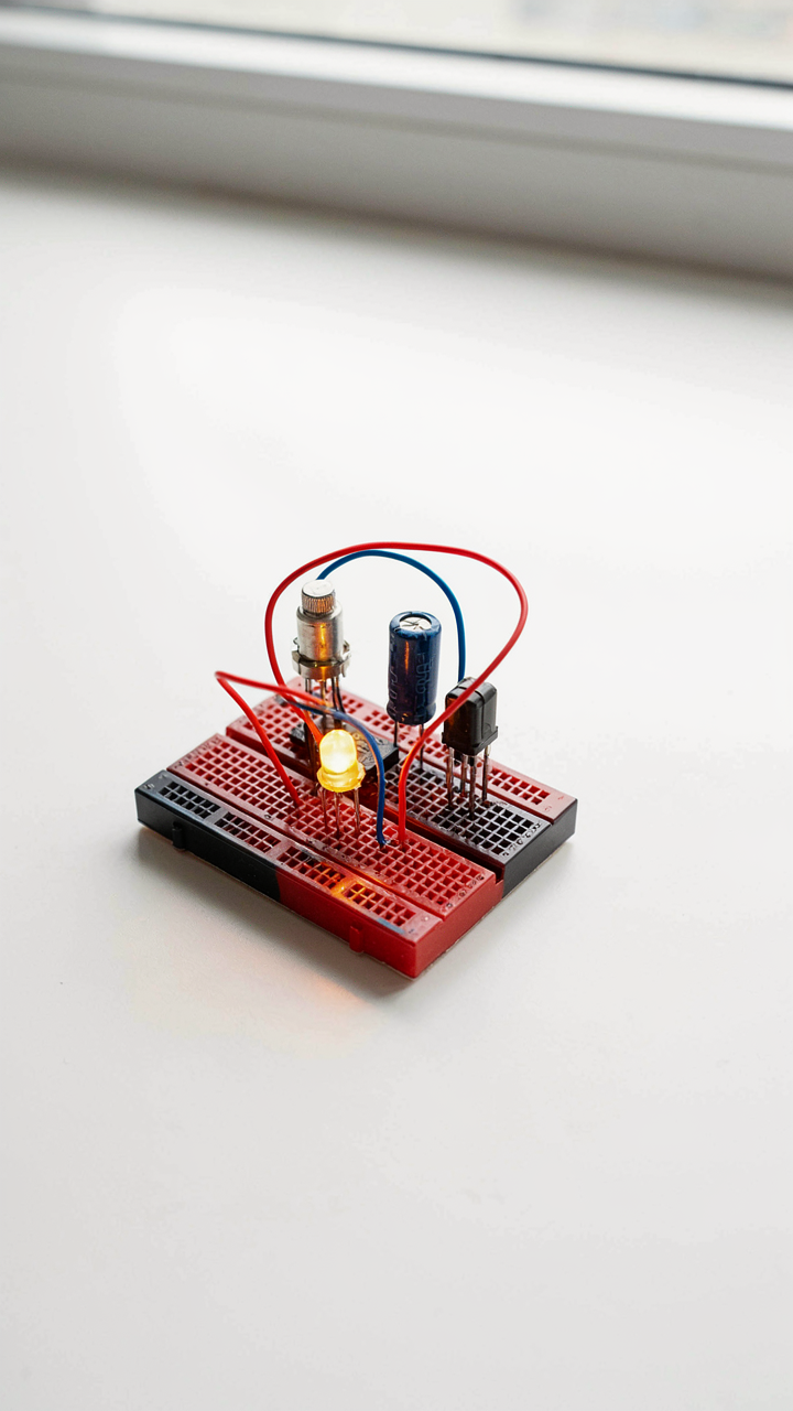
How Capacitors Store And Release Energy
You want to understand this because you’re tired of circuits feeling like magic. Here’s the mechanism: a capacitor is just two metal plates separated by an insulator. When voltage appears across those plates, electrons pile up on one side and deplete from the other, creating an electric field. That field holds energy. When you give the capacitor a path to discharge, it releases that energy back into the circuit as current.

A simple LED flasher uses this cycle deliberately. The capacitor charges through a resistor until it reaches a threshold voltage. Then a transistor or other switching component opens a discharge path, the capacitor drains through the LED, and the cycle repeats. The resistor controls how fast the capacitor charges. The capacitor size controls how much energy releases each cycle. Adjust either one and you change the flash rate.
When The Circuit Oscillates On Its Own
Physics calls this oscillation, and your flasher circuit is a mechanical oscillator wearing electrical clothing. Instead of a pendulum swinging back and forth, you have voltage swinging between charged and discharged states. The common mistake is thinking you need a complicated timing circuit. You don’t. A single transistor, resistor, and capacitor create oscillation because the capacitor charges and discharges at different rates through different paths.
Build this circuit: connect your capacitor to charge through a high resistance value, but discharge through the LED and a lower resistance. The capacitor hits the transistor’s threshold, the transistor fires, the capacitor drains fast, the transistor shuts off, and the cycle restarts. No clock signal required. The component values dictate the on-off timing. Change the charge resistor and the LED stays dark longer between flashes. Change the discharge path and the flash duration shortens.
Why “Fritzing” Projects Fail: Beyond Pretty Pictures In Electronics Projects DIY

Component Tolerances: The Hidden Variations
You want your circuit to work exactly like the diagram. That’s why this stings: your components won’t. You buy a 220-ohm resistor and it lands somewhere between 198 and 242 ohms depending on the batch, temperature, and how the manufacturer’s tolerance rating actually works in practice. Most people ignore this entirely.

In manufacturing, tolerance is the acceptable range of deviation from a stated value. A 5% tolerance resistor swings 10 ohms on either side of nominal. An LED’s forward voltage isn’t fixed at 2V—it drifts with current, temperature, and age. Your “simple” circuit absorbs these variations silently until it doesn’t. The LED dims, brightens unpredictably, or dies early because you designed around a fantasy spec sheet instead of real-world drift.
Breadboard Limitations: Parasitic Capacitance And Resistance
Your breadboard looks clean on camera. It’s garbage for actual circuit behavior. Breadboards introduce stray capacitance between adjacent holes and resistance in each contact point that soldered connections never produce. This matters the moment your circuit has any speed or precision requirement.
A jumper wire connection on a breadboard has measurable resistance—typically 50 to 100 milliohms per contact. Stack five connections in series and you’ve added half an ohm of loss that throws your voltage calculations off. Worse: the capacitive coupling between rows creates noise that kills predictable LED behavior. Your circuit “works” on breadboard, then fails the instant you solder it. Breadboard hides failures instead of revealing them. Test your actual design with permanent connections before declaring it functional.
The Information Highway: How Electrons Communicate In A Simple Led Chasing Circuit
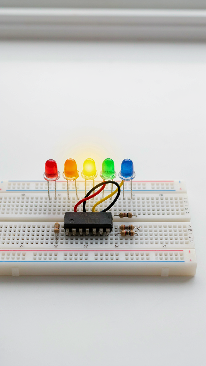
Binary Signals: On Off As Data
You want to understand this because it makes you feel like you grasp how computers work. Here’s the actual mechanism: in a chasing LED circuit, each LED exists in one of two states—conducting or blocked—exactly like a binary digit in computer science maps onto a transistor. Current flows through the LED or it doesn’t. No middle ground. A microcontroller or 555 timer IC sends voltage pulses to each LED pin in sequence. When the pin goes high (usually 5 volts), the LED lights. When it goes low (0 volts), the LED dies. The circuit doesn’t care about the intensity of the signal, only whether it crosses the threshold.

This threshold behavior is what makes chasing patterns possible. A 555 timer chip oscillates between high and low states at a frequency you set with a resistor and capacitor. It pushes current toward pin 1, then pin 2, then pin 3—each one gets its ON signal in turn. The circuit treats each moment as a discrete packet of information, just like data packets on the internet. You control the speed by changing the RC timing values. Slower timing means each LED stays lit longer before the signal moves to the next one. Faster timing creates the illusion of rapid motion.
Timing And Sequencing: The Rhythm Of Light Patterns
The speed at which electrons move is irrelevant to what you actually see. What matters is the switching speed, which you control through component values. In a simple chasing circuit, you need a clock signal that divides the ON time into equal intervals, then routes that signal through each LED position in order. This is sequencing. A counter IC like the 4017 decade counter does exactly this—it receives a clock pulse, increments an internal register, and activates a different output pin each cycle. The rhythm emerges from the math of the timing components, not from anything magical.
Most people miss that sequencing is just organized repetition. If your 555 timer oscillates at 1 Hz (one pulse per second), and you have a 4017 counter advancing on each pulse, then each LED lights for one second before the next one activates. Change the frequency to 10 Hz, and now each LED lights for 0.1 seconds. The human eye blends these intervals into smooth motion if the timing falls between roughly 10 and 30 Hz. Below that, you see distinct blinks. Above that, flicker becomes invisible. To build a working chasing circuit, set your RC timing so the 555 outputs between 10 and 20 Hz, wire the clock output to the counter’s clock pin, then run each counter output through a resistor to each LED anode.
Electricity Crafts For Kids: Not Just Play, But Real World Physics

When Current Stops, Nothing Happens
You want your kid to “understand electricity” without buying expensive kits or hiring tutors. Here’s the mechanism nobody states plainly: a simple LED circuit teaches what engineers call a closed loop, and most people never actually grasp why the loop matters. They know it matters. They don’t know why. An open circuit is a broken promise. Current cannot flow. The LED stays dark. Close the circuit, and electrons move. Light happens. That’s the entire game.

In physics terms, this is about resistance and continuity. A simple LED circuit requires an unbroken path from the battery’s positive terminal, through the LED and resistor, back to the negative terminal. Break any point in that path, and resistance becomes infinite. Electrons stop moving. The circuit dies. Kids see this instantly when they disconnect a wire. Observation drives understanding faster than any explanation ever could.
Light Is Electrons Doing Work
Physics borrows the concept of energy conversion from thermodynamics, and a simple LED circuit is pure conversion in motion. Electrical energy transforms into photons. The mechanism is direct: electrons move through the LED’s semiconductor material, lose energy as they pass through the junction, and release that energy as visible light. Nothing abstract happens. Energy enters one form, exits another.
Most LED explanations stop at “electricity makes light.” Wrong framing. The resistor in the circuit controls how many electrons move per second. Lower resistance means more current flows, more electrons collide with the LED’s junction, more light releases. Higher resistance means fewer electrons, dimmer light, less heat waste. A simple LED circuit teaches that controlling flow controls output. This is how every powered device on Earth works. Build one, measure it, change the resistor, and watch the behavior shift. That’s the protocol.
The Anatomy Of Failure: Common Traps In Led Circuit Projects
When Polarity Becomes A Weapon Against Itself
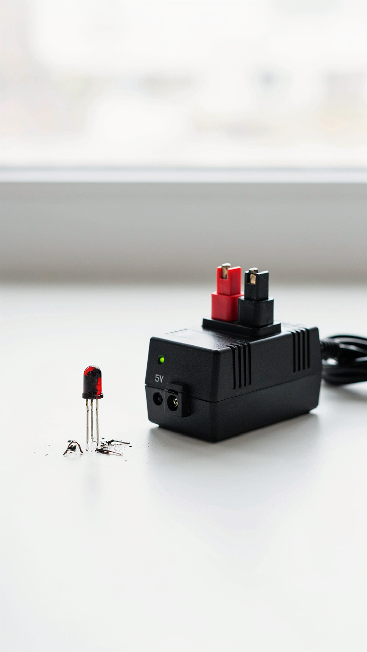
You’re reading this because you want to avoid looking stupid in front of someone, or you’re about to solder and don’t want to waste money. Here’s the mechanism: LEDs are diodes. Diodes only conduct current in one direction. The longer leg is positive, the shorter leg is negative. Install it backwards and you’ve created an open circuit that blocks all current flow.

The LED won’t just refuse to light up. In many hobbyist setups, people panic and reverse their battery or power supply polarity trying to fix it. Now you’ve got reverse voltage across the LED’s junction. The component fails silently or spectacularly depending on how much voltage you’re throwing at it. Your LED is dead. The battery is still fine. Replace the component, not the power supply. Polarity matters because electricity has direction, and diodes enforce it.
Getting The Resistor Math Right
Common advice says “just use any resistor and it’ll probably work.” That’s incomplete. Resistors limit current. Too little resistance and you push excessive amperage through the LED’s junction, burning it out in seconds. Too much resistance and the LED glows so faintly you think it’s broken.
The calculation is straightforward: (Supply Voltage minus LED Forward Voltage) divided by desired LED current equals required resistance. For a 5V supply with a typical red LED (2V forward voltage) and 20 milliamps current, you need a 150 ohm resistor. Get the value wrong and you either watch your LED burn instantly or question why you built anything at all. Measure twice, calculate once, solder with certainty.
Hand Crafts For Kids: Beyond Glued On LEDs

What Actually Conducts Electricity Here
You want your kid to feel smart without buying another plastic kit. Here’s what matters: not all materials conduct electricity equally, and that gap between “conducts” and “conducts well enough” is where most projects fail. Electricity follows the path of least resistance, like water finding a channel. Your job is finding materials that actually move current, not just theoretically.
- Graphite pencil leads: Carbon conducts electricity, but poorly. Resistance is high, so current flows slowly. Use for dimmed LEDs or educational demos, not bright output. Works best as a teaching tool about resistance, not a permanent circuit component.
- Play dough with salt: Salt water conducts through ionic movement, not electron flow like metals do. Ions carry charge between terminals. This teaches electrochemistry, but resistance drops as you add more salt. Creates heat and dough deterioration over time.
- Aluminum foil: Conducts like metal because it is metal. Electrons move freely. Thin enough to fold into contact points, thick enough to handle repeated bending without breaking. Best choice for actual function, worst for durability if creased repeatedly.
- Copper wire stripped bare: Gold standard for conductivity. Lowest resistance of the group. Doesn’t degrade. The reason it’s not “craft material” is because kids don’t find it exciting, but electrically it’s superior to everything else listed here.
- Paper clips and brass fasteners: Steel and brass conduct, but with higher resistance than copper. Oxidation increases resistance over weeks. Useful for temporary builds. Teach kids that metal quality matters to circuit function, not just whether it’s “metal.”

The mistake parents make is treating conductivity like a binary: it works or it doesn’t. It doesn’t. Resistance exists on a spectrum. Pencil lead will light an LED, but dimly and unreliably. That’s not failure. That’s physics showing itself. Build the project anyway, then measure voltage drop and discuss why the LED glows weak.
Where Connections Actually Fail
The standard advice says “make sure it touches.” That’s incomplete and misses the real failure point. Connections fail not because of loose parts, but because contact pressure decreases over time or environmental conditions degrade the surface layer. A tight connection today means nothing if oxidation or dust breaks it tomorrow.
Pressure matters more than you think. Two materials touching isn’t contact. Electrons need a channel. Surface oxidation on aluminum or copper creates an invisible barrier. When you press a battery terminal against aluminum foil, you’re breaking through that oxide layer and establishing electron flow. Stop pressing, and the oxide returns. Humidity accelerates this. Your kid’s craft made today might work tomorrow and fail next week, and they’ll think they broke it. They didn’t. Chemistry did.
The Minimalist’s Led Circuit: Achieving More With Less
Fewer Parts, Real Results
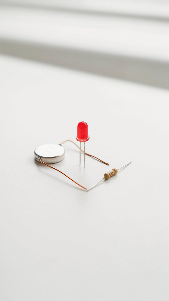
You want to look smart by building something complicated when the actual skill is knowing what to remove. Here’s the mechanism: every component you add increases failure points, cost, and debugging time exponentially. In circuit design, this principle mirrors the concept of signal-to-noise ratio from information theory. Your LED circuit works because the right parts transmit the intended behavior. Everything else creates static.

A basic LED circuit needs exactly four things: power source, resistor, LED, and return path to ground. That’s it. Most hobbyists add switches, extra resistors, capacitors, and components they don’t understand because tutorials show them. Remove the noise first. Build the minimum viable circuit, verify it works, then add only what solves a real problem.
Battery Life Through Intentional Limits
The common advice says “use a lower voltage source” or “add a capacitor.” Both miss the actual lever: you control current draw through resistor selection, and current draw is what drains your battery. Ohm’s law isn’t a suggestion; it’s your constraint. If you want extended runtime, you calculate the exact resistor value needed to deliver just enough current for visible light output, not excess.
Most people choose resistors too conservatively, wasting battery energy as heat in the resistor instead of in the LED. The right approach: determine your LED’s forward voltage and desired current from its datasheet, apply the formula (Power Supply Voltage minus LED Forward Voltage) divided by desired current. This single calculation extends battery life by weeks compared to guessing. Then measure actual runtime under real conditions and adjust downward until the LED dims noticeably, then back up one step.
The Illusion Of Complexity: Your Biggest Barrier Isn’t The Circuit, It’s Your Underdeveloped Mental Model Of Energy Itself
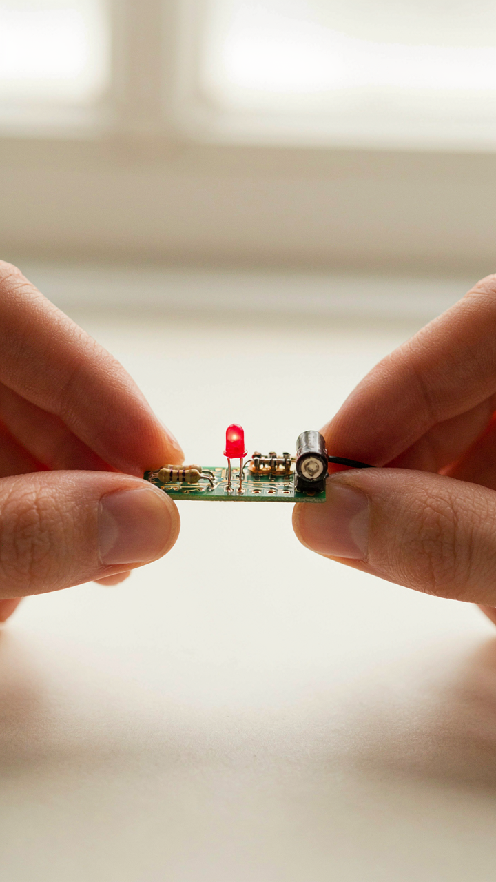
Most people never build a simple LED circuit because they’ve accepted the lie that electricity is complicated. It isn’t. Electrons move. Voltage pushes them. Resistance slows them down. That’s the entire game. Your real problem isn’t understanding circuits. It’s that you’ve never actually seen energy move with your own hands. Build one today. Connect a battery to an LED through a resistor. Watch light appear. Everything else in electronics flows from this single moment of clarity.