
The Photocell Fallacy: Why Your LDR Is Lying To You

When Your Resistor Stops Resisting
You want the circuit to work first try so you don’t look stupid troubleshooting in front of someone. The real problem: you’re treating an LDR like a simple on-off switch when it’s actually a variable resistor that behaves differently depending on how you wire it. An LDR doesn’t have a magic threshold where light flips a switch. It has a resistance curve that changes gradually across the entire visible spectrum. Most DIY guides skip this and just say “connect it in series” without explaining what actually happens to your voltage at different light levels.
The mechanism from signal processing applies here: your LDR is a transducer that converts light into resistance, but transducers only work as intended when you read their output correctly. If you wire it wrong, you’re not detecting light. You’re detecting nothing, or worse, detecting noise. The resistance of a typical LDR ranges from about 200 ohms in bright daylight to 200,000 ohms in complete darkness. That’s a thousand-fold change. Your circuit needs to amplify that change or measure it accurately, or you’ll end up with a light sensor that doesn’t sense.
Reading The Actual Signal, Not The Myth
Most advice tells you to use a voltage divider and call it done. This is incomplete. A voltage divider does work, but only when you understand what voltage you’re actually measuring at the midpoint. The problem most builders hit: they pick arbitrary resistor values, power up, and wonder why the transition happens at the wrong light level. You need to calculate the exact voltage at your detection threshold before you touch a soldering iron.
Here’s the real sequence: measure your LDR’s resistance in the exact lighting conditions where you want the circuit to switch, then work backward to pick your fixed resistor value. If you want the night light on at dusk, take the LDR resistance reading at dusk and use that to size your voltage divider so the midpoint voltage triggers your comparator or transistor gate right at that resistance value. This takes ten minutes with a multimeter and eliminates weeks of “why isn’t this working” frustration. Skip this step and you’re guessing.
Minimalist Illumination: The ‘Less Is More’ Diode Principle
Which LED Actually Works For Night Light Duty
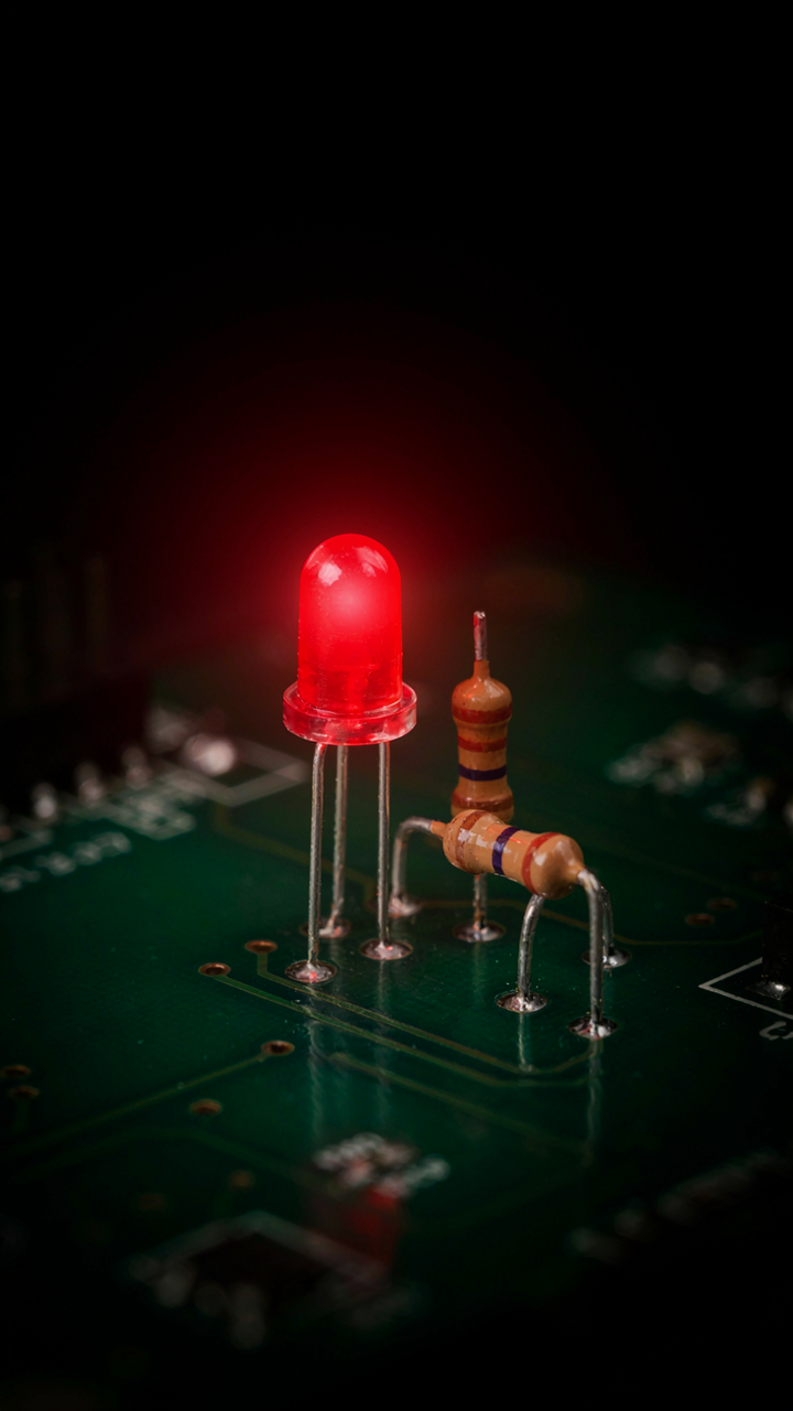
You want to pick an LED that looks impressive on a spec sheet but costs nothing to run. That’s the real motive here. But specs lie. The mechanism that matters is forward voltage drop and luminous efficacy. Forward voltage determines how much circuit current the LED actually demands at a given brightness. Efficacy tells you how many lumens you get per milliwatt burned.

A standard red LED sits around 1.8 to 2.0 volts forward voltage. A blue or white LED demands 3.0 to 3.5 volts. This matters because in a night light circuit powered by a 9V battery or AC adapter, you’re burning the difference as heat in your current-limiting resistor. Pick red or amber. They waste less energy before the photons ever leave. Use a 20-milliwatt LED rated for continuous duty, not a 100-milliwatt part you’ll run at 10 percent brightness.
Stopping The Resistor From Becoming A Heater
Everyone says add a resistor. Nobody says most people size it wrong and create phantom drain without even knowing it. The mechanism is Ohm’s Law applied backwards. Your resistor’s job is to drop voltage and limit current in series with the LED. Too small a resistor and your LED draws excessive current and dies early. Too large and you’re wasting circuit power as heat while the LED barely glows. The real cost of a night light is the milliwatts the resistor burns when nobody’s even looking at it.
Calculate the resistor value this way. Take your supply voltage minus the LED’s forward voltage. Divide by your target current, usually 10 to 15 milliwatts for a soft night light glow. A 1/4-watt carbon film resistor handles this all day. Use tolerance specs within 5 percent so you hit your intended current. Don’t guess. The resistor determines whether your circuit sleeps or stays hungry.
Automatic Night Light Circuit: Beyond The On/Off Switch

Setting The Threshold Without Guessing
You want the light to turn on automatically so you don’t have to think about it, which means you’re really after a system that responds to actual light levels, not your memory. The mechanism is threshold calibration: you’re setting a voltage trigger point on your light sensor where the circuit switches states. A CdS photoresistor’s resistance changes with illumination, and your job is tuning the voltage divider network so the switch happens at the exact lux level you need, not randomly somewhere in the dark.

Most people set threshold by trial and error in their living room at night, which is backwards. You need a reference: measure actual ambient light with a phone lux meter at the moment you want the circuit to activate, then build your resistor values to hit that voltage at your op-amp or comparator input. Use a potentiometer as your voltage reference initially, dial it in during real conditions, then replace it with fixed resistors that match. Your goal is a clean transition, not a guess.
Hysteresis Stops The Flicker Trap
Cybernetics teaches feedback loop stability through hysteresis: the system resists tiny perturbations by requiring a larger input change to reverse state than to create it initially. A diy night light circuit without hysteresis is a flicker machine. When your photoresistor sits right at the threshold voltage, ambient light bounces off walls, dust moves, your sensor drifts slightly, and the output toggles on and off 60 times per minute because you set the trigger too tight.
Install hysteresis by adding positive feedback: wire a resistor from your op-amp output back to the non-inverting input. This creates two thresholds: a higher voltage to turn the light on, a lower voltage to turn it off. The gap between them kills the oscillation dead. Calculate the resistor values using the hysteresis formula based on your supply voltage and desired window width, then test with a variable light source to confirm the light stays locked in the on or off state as you sweep brightness across the threshold zone. No flicker means your circuit works.
Powering The Dark: The Unseen Energy Drain
Which Battery Actually Lasts
You want to know which battery won’t die on you in three weeks because you’re already frustrated with buying replacements. Here’s the mechanism: battery chemistry determines discharge rate, and alkaline cells self-discharge at roughly 2-3% per year while sitting unused, but your night light circuit pulls current constantly, so chemistry matters more than capacity alone.

Alkaline batteries (AA, AAA) work fine for circuits pulling under 50 milliamps continuously. They’re cheap and widely available, but they’ll drain in months, not years, because your light runs every night. Lithium cells cost more upfront but self-discharge slower and handle temperature swings better, making them the real choice if you live somewhere cold. NiMH rechargeables seem smart until you realize they self-discharge faster than alkalines when idle, defeating the point of a permanent fixture. The circuit’s current draw determines which battery survives long enough to matter.
Solar Charging Replaces Replacement
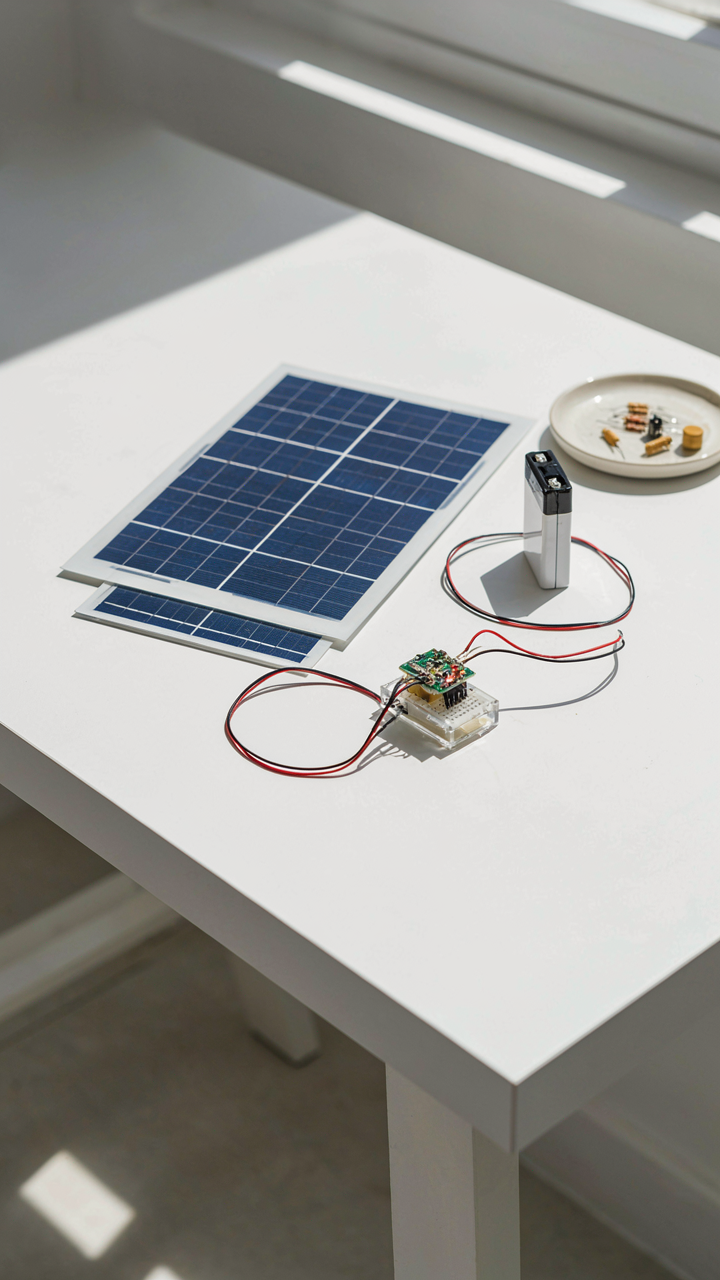
People talk about going solar for night lights like it’s some environmental flex. Actually, it’s just thermodynamics: you’re using photons to move electrons during the day so your circuit doesn’t need battery replacement. A small solar panel (0.5 to 2 watts) feeds a battery during daylight hours, and your night light circuit draws from that stored charge after sunset.
The real constraint is panel positioning and climate. Your solar panel needs direct sunlight for at least four to six hours daily to charge enough for a full night of operation. Use a charge controller circuit between the panel and battery to prevent overcharging. A simple diode works in a pinch, but a dedicated IC like the TP4056 gives you better control over charge termination. Mount the panel on a roof or south-facing wall where it gets unobstructed light. Cloudy regions will see degraded performance, but the system still beats swapping batteries every season.
Night Light Circuit Using Op Amp: Precision, Not Overkill
When You Actually Need The Op Amp
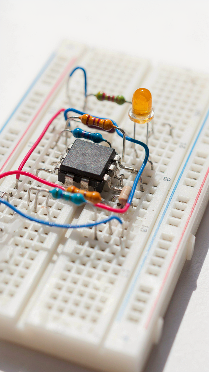
You want an op-amp in your night light because it sounds smarter than a transistor. Here’s the real reason to use one: you need a threshold voltage that doesn’t drift with temperature or power supply noise. A basic transistor switch drifts. An op-amp configured as a comparator holds its trigger point steady. The mechanism is negative feedback. It locks the switching voltage to a stable reference, not to whatever the power rail decides to do that day.

Most night lights don’t need this. A 2N2222 transistor with a photoresistor works fine for hobbyist use. But if you’re powering this from a phone charger that wobbles between 4.8 and 5.2 volts, or if ambient temperature swings fifty degrees, the transistor trigger point will creep. The op-amp won’t. That’s the tradeoff: complexity for stability. Don’t add it unless drift is your actual problem.
Sharp Switching Means Consistent Action
Comparator circuits weaponize the op-amp’s input stage, borrowing the concept of threshold detection from signal processing to create a hard on-off boundary. Feed your photoresistor voltage into the non-inverting input and a fixed reference voltage into the inverting input. The op-amp’s open-loop gain amplifies even microvolt differences into a clean rail-to-rail output swing. Your LED flips decisively at the exact light level you set, no fuzzy zone.
Wire the reference voltage using a voltage divider from your power supply. Use a 10k and 100k resistor to set the threshold at, say, 2.5 volts. When ambient light drops below that point, the photoresistor resistance climbs, the comparator input dips, and the output goes high. Use a 1N4148 diode across the load to protect the op-amp from inductive kickback if you’re driving a relay. The comparator doesn’t care if the input drifts slowly, only that it crosses the threshold.
Electronics Projects For Beginners: Skipping The Obvious
What You Actually Need To Buy
You want permission to skip the $200 starter kit and still build something that works. The mechanism is simple: a night light circuit has three functional requirements, not ten. Everything else is noise designed to make retailers money.
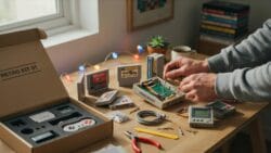
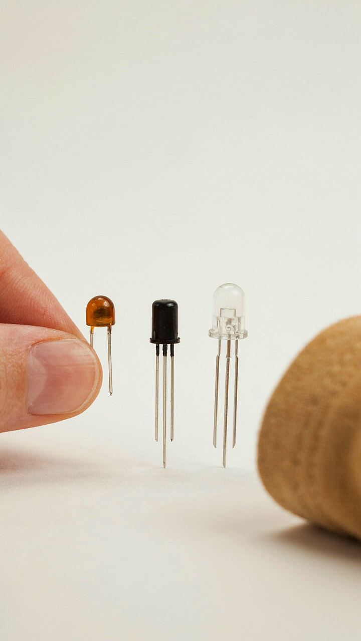
A light-dependent resistor (LDR) changes resistance when light hits it. A transistor switches power based on that resistance change. An LED lights up when power flows through it. Everything beyond those three components either amplifies the signal or protects the circuit from damage. You need what solves the problem, not what looks complete.
- LDR (photoresistor): Detects ambient light. Resistance drops from 100k ohms in darkness to under 1k ohms in bright light. Pick one rated for visible spectrum sensitivity.
- NPN transistor (2N2222 or 2N3904): Amplifies the signal from the LDR and switches the LED on or off. These cost under a dollar and handle the current load.
- LED and resistor: A standard 5mm LED and a 220-330 ohm current-limiting resistor prevent the LED from burning out. The resistor value depends on your power supply voltage.
- Power supply (4.5V to 9V): A battery pack or wall adapter. Lower voltage limits brightness but simplifies the build. Higher voltage requires a regulator.
- Breadboard and jumper wires: Lets you test before soldering. Skip permanent solder joints until the circuit works and you understand why each connection matters.
The trap most beginners fall into is buying component packs with fifty resistors and twenty LEDs. You use three components total. A breadboard, three wires, and the five items above solve the entire problem. Start there, then expand if you need to adjust sensitivity or brightness.
Why Your Circuit Won’t Work (And How To Actually Fix It)
Everyone gets told to “check your connections” and “make sure the polarity is correct.” That’s incomplete garbage. The real reason circuits fail is that beginners don’t understand the actual mechanism forcing current to flow. They wire things and hope, rather than trace why voltage moves where it moves.
Here’s what actually happens: when light hits the LDR, its resistance drops. If the LDR resistance drops below a certain threshold, the voltage at the transistor’s base rises high enough to turn it on. The transistor then conducts current through the LED. If nothing lights up, one of these three stages broke. Your job is identifying which one. Use a multimeter to measure voltage at the LDR in darkness versus bright light. A change confirms the LDR works. Measure at the transistor base next. If voltage there doesn’t change when light changes, the wiring between LDR and base is the problem. If the base voltage changes but the LED stays dark, the transistor or LED is faulty, or the current path from collector to emitter is broken.
The common mistake is reversing LED polarity. The longer leg (anode) connects to positive, the shorter leg (cathode) connects to negative through your current-limiting resistor. Backwards polarity blocks all current flow. A second mistake is using a base resistor that’s too large. If the resistance between the LDR and transistor base exceeds 10 megohms, not enough current reaches the base to turn the transistor fully on. The LED glows weakly or not at all. Test this by substituting a 10k ohm resistor in place of your base resistor. If the LED lights up bright, your original base resistor was starving the transistor. The third mistake is powering a 9V circuit without a current-limiting resistor on the LED. The LED draws maximum current and burns out instantly. Start with 4.5V and a 330 ohm resistor until you understand how current scales with voltage.

Paper Circuit Ideas: The Unconventional Materials Advantage
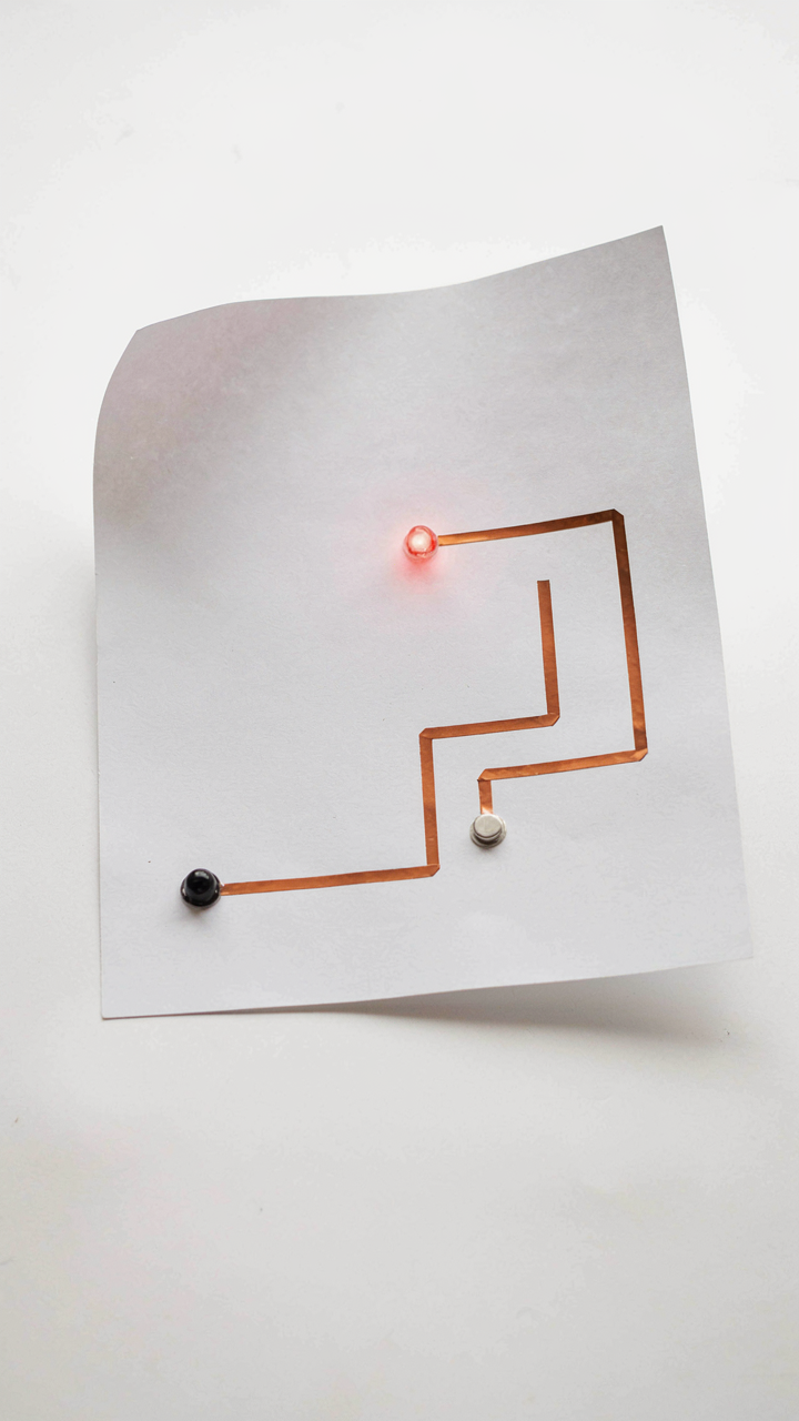
Conductive Inks And Tapes Replace Wires
You want to skip the mess of soldering because you think it makes your project look cleaner or more legitimate. The real mechanism is simpler: conductive inks and tapes eliminate connection points where corrosion kills your night light after weeks. Silver-based conductive ink prints directly onto paper or flexible substrates. Copper tape adheres with pressure alone and accepts solder joints where needed, or works standalone for low-power circuits like a light-sensing night light that draws minimal current.
Standard wiring creates mechanical stress at joints. Conductive tape distributes resistance evenly across its surface, meaning your photoresistor connection to the power rail stays stable without heating up. Apply copper tape along printed traces, overlap joints by at least half an inch, and press firmly to ensure contact. Your night light circuit now tolerates vibration and temperature swings that would snap a soldered wire or crack a board.
Flexible Sensors Mounted On Electronic Paper
Circuitry borrows from materials science the concept of impedance matching, where the sensor’s electrical behavior aligns with the circuit it feeds into. A photoresistor mounted on e-paper substrate faces the same impedance challenge as a rigid PCB version, but the substrate itself becomes part of your design system instead of fighting against it. Electronic paper backing holds the photoresistor flat while letting you bend the entire light-sensing layer without breaking connections.
This approach eliminates the separate “sensor module” problem. You’re not gluing a discrete part onto a board and hoping the wire stays attached. Instead, the photoresistor prints or bonds directly onto flexible material alongside the resistor divider network that conditions its signal. The paper itself becomes structural and electrical at once. Mount this assembly into your night light housing so it folds or curves around corners, giving your sensor a wider field of view without adding bulk or breaking anything during assembly.

The Day Night Switch Circuit Diagram: Deconstructing Complexity
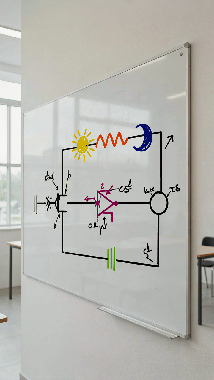
Build The Schematic Right
You want this section to feel like you’ve figured something out that others missed. The real mechanism is simple: you haven’t. Most DIY night light circuits fail because people copy schematics without understanding the load path. The schematic itself is straightforward—power source, photoresistor, transistor, relay or LED driver, output load. Draw it left to right. Current enters at the positive rail, flows through your light-dependent resistor in series with a fixed resistor forming a voltage divider. That junction feeds your transistor base or comparator input. The collector or output drives your load. Ground completes the loop.
The photoresistor sits in darkness at high resistance, typically 100k to 1M ohms. This creates high voltage at the base of your NPN transistor. High base voltage means the transistor conducts, pulling the output low or sinking current, which activates your relay or LED circuit through an inverse logic gate if needed. In daylight, the photoresistor drops to a few hundred ohms, base voltage falls, transistor cuts off, output goes high, and the night light disengages. This isn’t optional architecture—it’s the only configuration that works without added complexity.
Find Failures Before They Find You
Troubleshooting a dead circuit means isolating which stage quit working. Start by measuring voltage at the photoresistor junction under controlled light conditions. In darkness, you should see 4 to 9 volts if using a 9V supply with a fixed resistor matched to your photoresistor specs. In bright light, voltage should drop to 1 to 2 volts. If voltage doesn’t change between light and dark, your photoresistor is either disconnected or has failed to an open circuit—replace it.
If voltage changes correctly but your load doesn’t respond, the problem lives downstream in the transistor or relay stage. Measure base voltage directly. If it swings properly but the collector voltage doesn’t respond, your transistor is damaged or in the wrong configuration. If collector voltage changes but your relay doesn’t click, the relay coil is broken or your driving transistor can’t source enough current. Use a multimeter to confirm continuity on the relay coil and test each component in isolation before reassembling the full circuit.

The ‘Perpetual Light’ Protocol: Engineering Autonomy

Build Once, Never Adjust Again
You want this because you’re tired of maintaining things. The mechanism is simple: a night light circuit that truly operates unattended needs three locked parameters—sensor threshold, component tolerance, and power delivery stability. Most DIY builds fail here because they treat these as afterthoughts instead of design constraints. The photoresistor drifts. The power supply sags under load. The relay chatters. Your circuit dies in silence while you’re not watching.
Design for unattended operation by eliminating drift first. Use a photoresistor rated for your specific lux range, then overdim the LED by 20 percent compared to your maximum brightness target. This gives you margin when the photoresistor ages or environmental dust accumulates on its lens. The LDR will lose sensitivity over 2 to 3 years, but a slightly dimmer light still functions. Underdim and you’ll get false triggers or dead zones.
Adapting To Change Without Redesign
Military systems call this concept “design for obsolescence management”—when you assume your environment will shift and you plan for it anyway. Your night light circuit faces the same pressure: LED brightness degrades, power supply ripple increases with age, sensor sensitivity drifts. Build resilience by using a potentiometer trim pot on the threshold voltage, not a fixed resistor divider.
This single change makes your circuit adaptive instead of brittle. A fixed 100k resistor divider means you’re locked into one trigger point forever. A trim pot means you can adjust threshold in 30 seconds if ambient light conditions change, if the LED dims, or if you move the circuit to a different room with different baseline lighting. Calibrate it once per year, not once and abandon it. The mechanism: variable voltage divider at the comparator input, not hard-coded resistance.
The Real Obstacle Isn’t The Circuit Diagram; It’s Your Addiction To Over-optimization

Most people never build a diy night light circuit because they’re waiting for the perfect design. They research endlessly, compare components, debate resistor values. Meanwhile, someone else already soldered theirs together with whatever parts they had. Your job today is to grab a photoresistor, a transistor, and an LED. Stop thinking. Start building. Done beats perfect every single time.



