The Illusion Of “Beginner Friendly” Electrical Testing Tools

What Online Tutorials Actually Hide
You want to feel competent without looking stupid. That’s why “beginner-friendly” guides exist. Here’s the mechanism: most tutorials simplify the multimeter into a reading device, not a diagnostic instrument. They show you how to take a voltage measurement but never explain why that measurement matters or what faulty readings look like. The gap between pushing a button and interpreting data is where beginners stay stuck.
The real problem isn’t the tool. It’s that tutorials treat the multimeter like a thermometer—you point it at something and get a number. Electricity doesn’t work that way. A multimeter reveals system behavior under specific conditions. Without understanding what conditions you’re testing, what range of values signals a working component, and how to isolate variables, you’ll collect data that means nothing. This is why people measure voltage on a dead circuit and think the multimeter is broken.
Why You’re Actually Using It Wrong From Day One
Think of circuit diagnosis like forensics: you’re not just collecting evidence, you’re building a chain of causation. The multimeter is your evidence kit. Most beginners fail because they skip the fundamental question: what state should this component be in right now? Without that baseline, every reading becomes noise.
The hidden complexity is selecting the right mode and range before you touch the component. Most tutorials skip this step or bury it. You must first determine if you’re measuring DC or AC voltage, then choose a range that captures the expected value without damaging the meter. Then you apply the probe correctly to avoid short circuits or false readings. Skipping any step corrupts your data. Start every measurement by naming what you expect to find, then verify the meter is set to find it.
The “Multi Meter” Triad: Voltage, Current, And Resistance Decoded
What Voltage, Current, And Resistance Actually Do
You want to understand this section because you’re tired of feeling lost when someone hands you a multimeter. Here’s the mechanism: voltage is electrical pressure. Current is the flow rate of charge. Resistance is what blocks that flow. Think of water through a pipe: voltage is the pump pressure, current is the gallons per minute, and resistance is anything constricting the pipe. A multimeter measures these three things because they control whether power reaches a device and how it behaves.

The reason these three exist together isn’t arbitrary. Physics calls it Ohm’s Law: voltage equals current multiplied by resistance. Map that onto troubleshooting: measure voltage to know if power arrives, measure current to know if it’s flowing properly, measure resistance to know if a component is damaged or open. Most beginner advice stops at “these are the three functions.” That’s incomplete. You need them together because each one tells you something the others don’t. A circuit can have voltage but zero current if resistance blocks it completely.
Why You Measure Each One At Different Times
Most guides say “measure voltage first” and leave it there. That’s wrong. You measure each one based on what problem you’re actually solving, not on some universal sequence. Voltage tells you if power exists in the circuit. Measure it when a device won’t turn on or behaves erratically. Current tells you if the circuit is drawing power it should. Measure it when you suspect a component is burned out or a wire is loose. Resistance tells you if a component is good or failed. Measure it when everything else points to a single broken part.
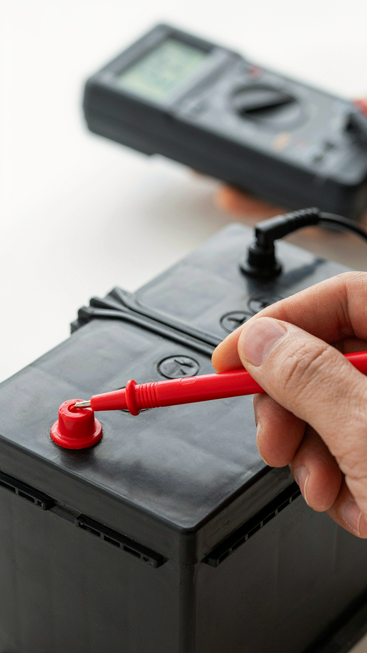
Context determines your measurement order. If a battery-powered toy stops working, check voltage at the battery terminals first. If voltage reads normal but the toy stays dead, measure resistance across the motor. If you’re diagnosing a wall outlet that feels weak, measure current draw on devices plugged into it. The multimeter is a diagnostic tool, not a magic wand: what you measure depends on what symptom you’re investigating.
Beyond The “On” Switch: The Calibrated Mindset Protocol

Check Your Meter Before It Checks You
You want to skip this part because it feels like bureaucracy, but a dead battery or broken probe costs you time and credibility. Here’s the mechanism: a multimeter is only as accurate as its last calibration point. Think of it like a scale at a gym—if it’s off by five pounds, every measurement downstream becomes noise.

Start with the physical inspection. Look for cracks in the meter housing, frayed probe wires, and corroded battery contacts. A damaged probe will give false readings that you’ll trust anyway. Then check the battery indicator on the display. If your meter has one, it should show green or adequate charge. Replace the battery if voltage is low, not when it dies mid-measurement.
Know Your Signal Before You Measure It
Diagnostic sequencing comes from electrical troubleshooting methodology: you never probe blind. Map the circuit path first, understand what voltage or resistance should exist, then set your meter to the right mode and range. Wrong mode plus wrong range equals either a blown fuse inside your meter or a reading so far off you’ll make a bad decision.
Ask three questions before the probes touch anything. What am I testing: voltage, current, or resistance? What’s the expected value based on the schematic or normal operation? What’s the maximum safe value my meter can handle in this mode? Write these down. Speed comes after accuracy. Your meter will protect itself in most cases, but your understanding protects you from drawing the wrong conclusion from a number on the screen.
Multimeter Symbols: Deconstructing The Secret Language Of Circuits
The Core Three: Voltage, Current, Resistance
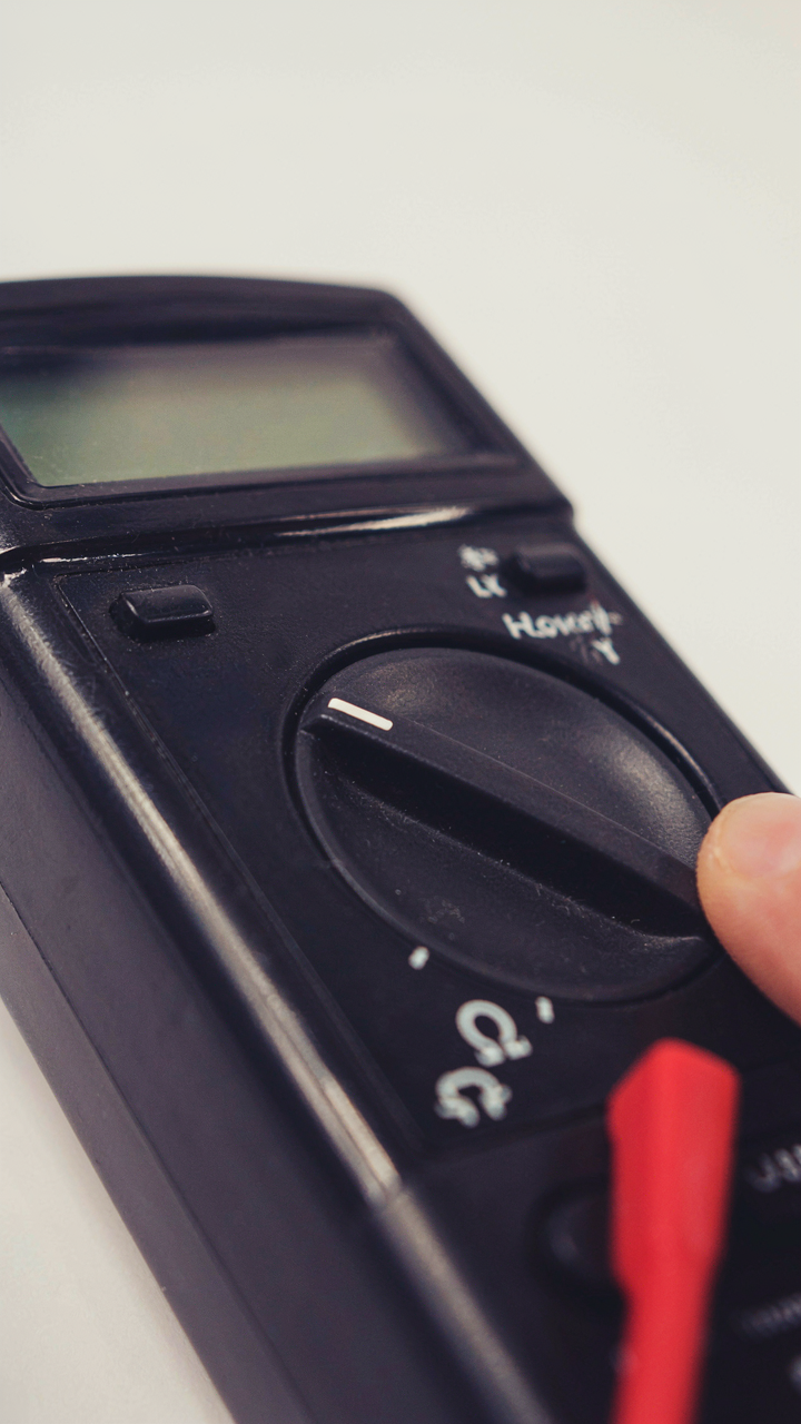
You want to feel competent without actually studying. That’s not happening here. The mechanism is simple: every symbol on your multimeter dial represents a different way electricity behaves, and you need to match the behavior you’re measuring to the right symbol or you get garbage data. Voltage measures potential energy between two points. Current measures flow rate. Resistance measures opposition to flow. These three are the entire foundation. Nothing else matters until you nail these.

The symbols look different across manufacturers, but the logic stays identical. A V with a line through it means DC voltage. A V with a wavy line means AC voltage. An A means current. An ohm symbol (Ω) means resistance. Stop treating these as decorative. Each one unlocks a specific measurement mode. Your multimeter physically switches circuits when you turn the dial. You’re not just changing a display, you’re routing electricity through different measurement paths. Pick the wrong one and you either get no reading or you damage the meter.
Continuity, Diodes, And The Rest
Physics borrowed the concept of gates from logic systems, and diode testing works the same way: it checks if current flows one direction but not the other. Continuity testing sounds exotic but it’s the simplest function you’ll use. It just checks whether electricity can flow through something. The symbol is often a sound wave or a straight line. You flip to that mode, touch both test leads to the circuit, and the meter beeps if current can move between the points. No beep means a break, a disconnect, a problem. That’s the entire protocol.
Diode mode tests semiconductors specifically. It sends a tiny current through the component and measures the voltage drop. If the diode conducts in one direction but blocks in the other, it’s good. If it conducts both ways or neither way, it’s dead. Frequency mode counts cycles per second in AC circuits. You won’t touch this until you’re fixing audio gear or power supplies. The mechanism is straightforward: each symbol corresponds to a physical measurement the meter performs, and your job is matching the component you’re testing to the right dial position.
The Circuit Breaker Mentality: Troubleshooting Like An Engineer

Think In Feedback Loops, Not Symptoms
You want to feel like you know what you’re doing without actually having to think. Here’s the mechanism: cybernetics teaches us that systems fail not randomly but through feedback loops—a component stops regulating input, output deviates, and the system either corrects itself or breaks. Your multimeter reveals which loop failed. Instead of testing random points hoping to find the culprit, you isolate by feedback: measure the input to a component, measure its output, identify where the signal deviates from expected range. That deviation tells you exactly which component lost control.

Most beginners treat troubleshooting like a guessing game. They probe around checking voltage at different spots until something looks wrong. This wastes time and teaches you nothing. Real troubleshooting works backward from the broken output. If a circuit powers a motor and the motor doesn’t spin, you know the output failed. Now measure backwards: voltage at the motor terminals, voltage at the component feeding the motor, voltage at the source. The moment the voltage changes between two points, that’s your failure point. The multimeter doesn’t find broken parts—it maps where information flow breaks down.
Catch Drift Before Collapse
Preventive measurement beats reactive scrambling every time. Components degrade gradually. A resistor’s value drifts upward. A capacitor loses capacity. A connection oxidizes and adds resistance. Your multimeter can detect these shifts while the circuit still functions. The mechanism is straightforward: measure component values under normal operation, record them, then check periodically. When a value deviates beyond tolerance, replace it before failure cascades through the system.
Take a power supply feeding an amplifier. If the output voltage reads 11.8V instead of its specified 12V, you might not notice yet. But measure again in two weeks and find 11.5V. That’s drift. The regulator component is failing. Catch it now with your multimeter, replace it, and the system stays operational. Ignore it and the voltage keeps dropping until the amplifier malfunctions or shuts down. Resistance measurements on connections and capacitor tests save far more time than emergency troubleshooting after the system dies.
Home Electrical Wiring: Unveiling The Invisible Network

Testing Household Circuits Safely
You want to feel competent around electricity without getting hurt. The mechanism is simple: electricity doesn’t care about your confidence. It follows physics. Your multimeter reads voltage, which is potential energy waiting to move through a conductor. Before touching any circuit, you kill the power at the breaker. You then use your multimeter to verify the power is actually dead, not just assumed dead. This is called testing for absence of voltage. It’s the only test that matters before you work.

Set your multimeter to AC voltage mode. Touch the black probe to the ground or neutral wire. Touch the red probe to the live wire you’re testing. If the screen reads zero or close to zero, the circuit is dead and safe. If it reads 120 volts or higher, power is still present. Never proceed. Your job is to confirm what the breaker switch promised. The multimeter is your proof that the system actually did what you asked it to do.
Spotting Wiring Problems
Most advice tells you to look for obvious damage and call an electrician. That’s incomplete. Your multimeter finds faults that look fine to your eye. Here’s what actually breaks in home wiring: resistance builds up where connections loosen or corrode. Think of it like traffic congestion. A wire should carry current smoothly. When resistance appears, the wire heats up, voltage drops unevenly, and devices malfunction before anything catches fire. Your multimeter measures this resistance in ohms.
Turn off the breaker. Set your multimeter to ohms mode. Disconnect one end of the wire you’re testing. Touch one probe to each end of the wire. A good wire reads near zero ohms. A failing wire reads higher, sometimes climbing into the hundreds. High resistance means corrosion, a loose connection, or internal damage to the conductor itself. Replace that wire or connection immediately. This test catches problems before they become emergencies.
Basic Electrical Wiring: From Theory To Tangible Connections
When A Wire Fails Silent
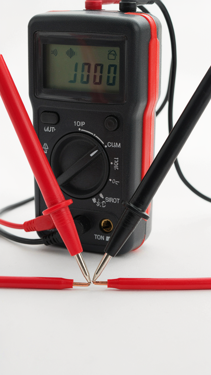
You want to know if something works without looking like you don’t know what you’re doing. That’s the real reason you care about continuity. The mechanism is simple: electricity flows in closed loops. A break anywhere stops the current. Your multimeter detects this by sending a tiny signal through the wire and measuring whether it bounces back. No return signal means a break exists.

Set your multimeter to continuity mode, marked with a sound wave symbol on the dial. Touch one probe to each end of the wire or connection you’re testing. If the meter beeps or shows near-zero resistance, continuity exists and the connection is intact. Silence or infinite resistance means the wire is broken or the connection is corroded. This tells you whether current can physically travel where you need it to go, which is the foundation of every functional circuit.
What Your Circuit Actually Consumes
The common advice skips this: most beginners measure voltage and never connect it to real power draw. Voltage tells you the push. Current multiplied by voltage tells you the work being done. Electricity in physics has a direct equivalent in economics: current is like cash flow, voltage is like margin, and power is like revenue. Your multimeter measures current directly on the amps setting.
- LED circuits: Typically draw 10-20 milliamps at 5 volts. Set your meter to the 200 mA range to avoid blowing the fuse inside your multimeter.
- Small motors: Draw 500 mA to 2 amps depending on load. Use the 10 amp setting for safety and accurate readings without internal damage.
- Resistive loads: Calculate watts by multiplying volts times amps. A 12-volt circuit pulling 1 amp consumes 12 watts of power.
- Battery drain test: Measure current draw in milliamps to diagnose parasitic loads or failing components in dormant devices.
- Series circuit verification: Current should read the same at every measurement point. Different readings mean a break or unintended path exists.
To measure current, insert your multimeter in series with the circuit. Break the connection, touch one probe to the power source, the other to the load. Current flows through the meter itself. Write down the reading and multiply by voltage to get total power consumption. This number tells you whether a component is working as designed or slowly burning through your battery.
Electrical Circuit Diagram: Reading The Blueprint Of Power

Translating Schematic Symbols Into Real World Measurements
You want to look competent without actually understanding what’s happening. The real mechanism here is this: a schematic is a translation layer between the designer’s intent and the physical reality your multimeter measures. Every symbol on a diagram corresponds to a specific electrical behavior you can verify with your meter.

Resistors appear as zigzag lines or rectangles. Capacitors show as parallel lines. Diodes are triangles pointing toward a line. Voltage sources are circles with plus and minus signs. When you see these symbols, you’re looking at promises about what your multimeter should read at specific points. A resistor symbol tells you resistance will exist between two nodes. A voltage source symbol tells you voltage will appear there. The symbol is the prediction. Your multimeter is the verification tool.
Using Diagrams To Anticipate Expected Multimeter Readings
Most beginners treat the diagram and the meter as separate events. Wrong. The diagram predicts your readings before you touch the meter. Schematic diagrams show node labels, voltage levels, and component values written directly on them for this reason.
If a diagram labels a node as 5V, your multimeter should read approximately 5V when you place the black probe to ground and the red probe on that node. If a resistor is labeled 10k ohms, your ohms mode should return close to that value when you measure across it without power applied. If a capacitor is rated 100µF, you know its capacitance range before testing. The diagram arms you with expected values. This eliminates guessing and forces you to ask why your actual reading differs from the schematic’s promise. That difference is where problems live, and now you know where to look for them.
Electronics Projects DIY: From Concept To Calibration

When The Circuit Fails Before You Build It
You want to look competent. You want to avoid the embarrassment of a dead project on your bench. That fear drives most people to skip the planning phase entirely and jump straight to assembly. The mechanism that separates working projects from burning components is voltage verification before power-on. Every circuit has a design voltage and a maximum voltage it tolerates. You measure both before current flows. A multimeter in DC voltage mode becomes your gatekeeper between intent and destruction.

Integration starts during schematic review, not after soldering. Before you touch a component, know what voltage each rail should carry and which pins expect which values. Your multimeter becomes a verification tool at three stages: after initial power connection to confirm the supply matches specs, mid-build to catch shorts before they cascade, and before connecting sensitive parts like microcontrollers or sensors. This isn’t extra work. It’s preventive maintenance that catches problems when they cost nothing to fix instead of after you’ve fried a $15 IC.
Diagnosis After Assembly Is Where Most People Fail
Common advice says “test everything at the end.” That’s lazy and expensive. By the time your circuit is fully assembled, a failed component could be anywhere in the chain, and tracing it means dismantling work. The real protocol is incremental validation: power sections one at a time, measure at known checkpoints, and document baselines. Think of this like a binary search algorithm from computer science, where each measurement eliminates half the possible failure points.
After assembly, start at the power supply. Measure input voltage, output voltage under no load, and output voltage when you connect the first stage of your circuit. Record these numbers. Move to the next section and repeat. If a reading deviates, you’ve narrowed the problem to one stage instead of guessing across the whole board. Check continuity on critical traces before measuring voltage on sensitive pins. Measure ground connections explicitly. A loose ground wire kills more beginner projects than component failures. Document every reading against your design specs, then identify which measurement breaks the chain.
How To Use Multimeter: Beyond The Manual, Into Mastery

Reading The Needle Without Hesitation
You want to feel like you know what you’re doing instead of guessing. The real mechanism is this: your multimeter displays raw voltage, resistance, or current, but your brain interprets it through noise. Every reading sits inside a band of acceptable variance. The needle or digital display will drift slightly due to environmental conditions, lead resistance, and contact pressure. This isn’t a flaw you’re missing. It’s built into the design. A one or two unit fluctuation on the display at higher resistance measurements is normal drift, not a broken component. Learn to read the trend, not the exact number. Watch the needle settle for two seconds before you trust the reading. On digital displays, ignore the last digit if it flickers. Your job is to detect the signal inside the noise, not hunt perfection that doesn’t exist.
The practical step: take three consecutive readings of the same circuit node without moving your probes. If two of three readings cluster within five percent of each other, that’s your true value. If all three scatter wildly, your probes aren’t making solid contact or the circuit is unstable. This filtering method works because it separates equipment variance from actual electrical change. Most beginners freeze on a single reading and misdiagnose the problem. You won’t.
Testing Live Circuits Without Burning Your Lab Down
Everyone warns you about safety without naming what actually kills you. The real risk is not voltage itself but your own hesitation creating a wrong probe placement. AC current kills. DC current above 50 milliamps burns tissue. But the actual failure mode is this: you reach across a hot breadboard without a plan, your hand twitches, and the probe slides into two live rails simultaneously. The multimeter becomes a short circuit. This doesn’t destroy most multimeters instantly because they have fuses. It destroys the circuit you’re testing and teaches you nothing. Plan your probe path before you touch anything. Know exactly where each probe lands. Imagine the worst contact mistake and physically position yourself so it can’t happen. Test with the circuit powered off first. Verify your meter settings before going live. Then measure DC voltage first, AC voltage second. Current testing comes last and rarely, because it breaks circuits.
When you must test a live circuit, use one hand only. Keep your other hand in your lap or behind your back. This prevents a path across your chest. Set your multimeter to the highest reasonable range first, then dial down once you confirm the voltage level. Never reverse probe polarity on DC while measuring. Never leave your probes in the circuit unsupervised. Remove them immediately after each reading and set them to a safe position on the bench before adjusting any settings.
The Only Barrier To Real Electrical Insight Is Your Own Intellectual Laziness
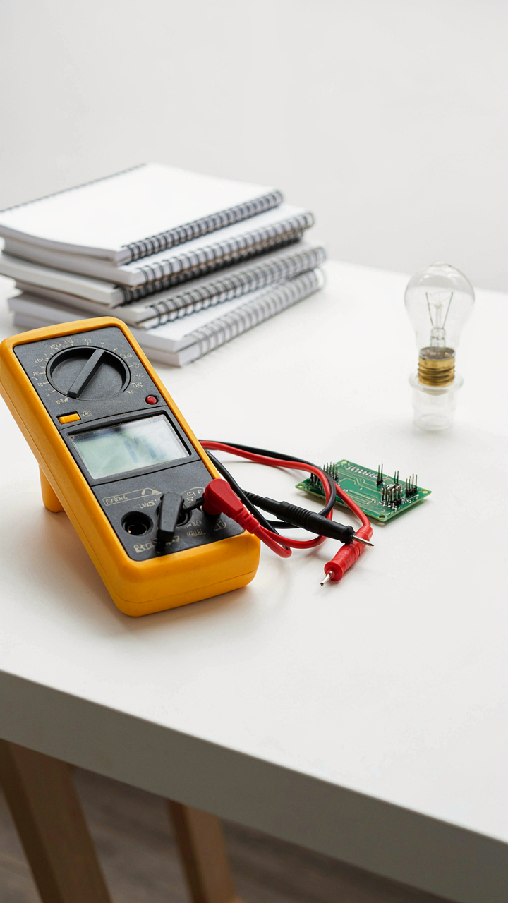
Most people buy a multimeter and never touch it again. They convince themselves it’s too complicated or they’ll learn it “later.” That’s not true. The barrier is that you haven’t forced yourself to fail with it yet. Pick a dead battery in your house today. Measure it. You’ll feel stupid for five minutes, then you’ll understand voltage. Understanding voltage changes everything about how you see electronics. Stop waiting for permission to be competent.