
The Thermal Domino: Understanding Heat Transfer On A Circuit Board
How Heat Moves Through Metal
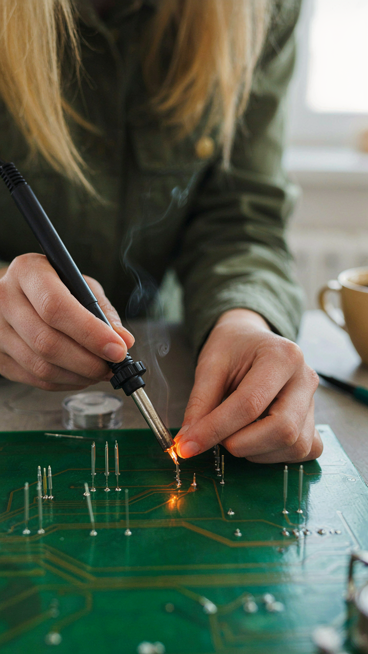
You want to know this because you’re terrified of creating solder bridges, and you think it’s random. It’s not. Heat transfer in soldering works like electrical current in physics: it follows the path of least resistance. The component lead is a conductor. The pad is a conductor. Heat flows from your iron through the lead into the pad because that’s the easiest route available. This path determines whether solder melts properly or pools where you don’t want it.
The mechanism is conduction. Heat travels through solid material by direct contact. Your iron touches the lead. The lead touches the pad. Thermal energy moves through both in sequence, melting the solder at the joint. The speed of this transfer depends on the material’s thermal conductivity and the surface contact area. A larger pad absorbs heat faster than a tiny one. A thick component lead conducts heat differently than a thin trace. Understanding this eliminates guesswork.
Radiation And Contact Heat Work Differently
Most soldering advice skips this entirely, and that’s a mistake. Radiant heat radiates outward in all directions from your iron tip. Conductive heat requires direct contact. On a circuit board, conduction does almost all the work. Radiation contributes noise, not signal. Your iron heats the lead and pad through direct contact, not by radiating heat into the air around them. The solder melts because the metal underneath reaches melting temperature, not because hot air touched it.
This distinction matters for bridge prevention. If you rely on radiant heat, your iron hovers near the board and heats everything nearby equally. Nearby components melt. Solder flows to unintended places. Conductive heat is targeted. You press the iron tip directly onto the joint you want to melt, heating only that specific connection. The thermal energy stays localized. Neighboring pads stay cool. This control is what stops bridges before they form.
Pre Flight Check: The Circuit Board’s Unseen Variables
Pad Metallurgy And Solder Adhesion
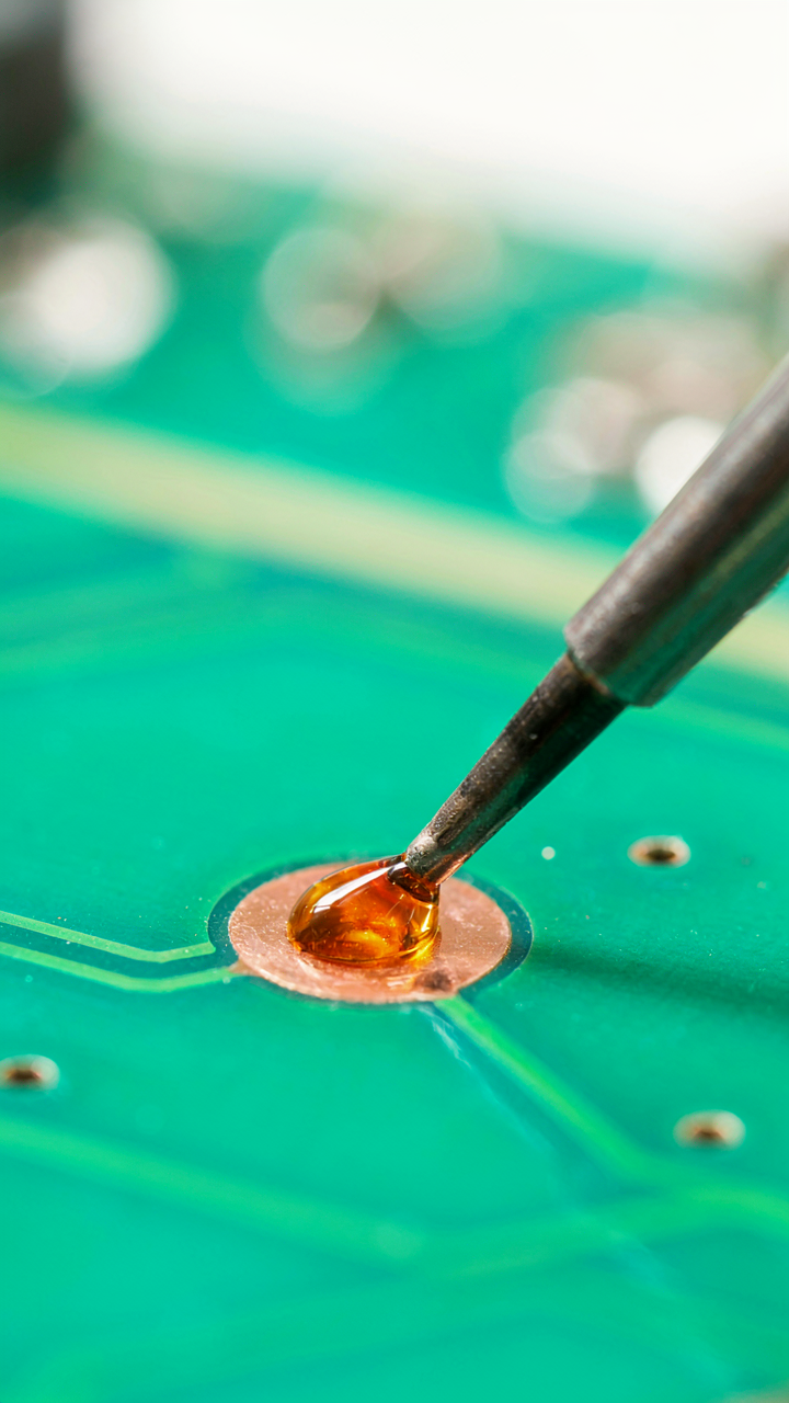
You care about this section because you want to believe technique alone determines your results. It doesn’t. The pad surface beneath your iron decides whether solder wets or beads up and rejects the joint. Think of pad metallurgy like soil composition in agriculture: you can have perfect planting technique, but infertile ground defeats you before you start.
Most circuit boards use copper pads finished with nickel or tin plating. Copper oxidizes fast. Old boards or boards stored in humid conditions develop oxide layers invisible to the eye but fatal to wetting. Your solder cannot flow across oxidized copper, no matter how hot your iron runs. Clean the pad mechanically if oxidation is visible, then apply fresh flux immediately before soldering.
Flux Activation: Cleaning Without Scrubbing
The common advice says “just clean with an old toothbrush.” This is incomplete. Flux’s job is to remove oxides during the heating phase, not after. If you scrub pads before soldering, you strip away the flux’s protective layer and invite new oxidation in seconds. The mechanism works the opposite way from what most people assume.
Active flux begins melting around 100-150°C and reaches peak reactivity between 180-220°C, depending on type. This is well before your solder melts. Let the flux do the work. Apply it to the pad and joint area, heat the assembly, and let the flux’s chemical action clear oxides as the temperature climbs. Wipe excess flux away after the joint cools, not before.
The Solder Flow Protocol: Directing Molten Metal

Surface Tension Pulls Solder Into Tight Spaces
You want to believe technique matters more than physics because that lets you blame your hands instead of your understanding. Physics is the real opponent. Borrow from fluid dynamics: solder behaves like a liquid seeking equilibrium, and surface tension acts as an invisible boundary that constrains where molten metal actually goes.

Molten solder clings to heated copper and tin surfaces because the metal atoms bond stronger to those substrates than to air. This capillary action—the same force that draws water up a paper towel—naturally pulls solder into gaps between component leads and pads. The narrower the gap, the stronger the pull. This is why a 0.5mm spacing between leads creates a solder bridge: the capillary force overcomes gravity and drags metal across the gap before the joint even cools.
Gravity Is Your Only Brake On Molten Flow
Most guides ignore this: gravity doesn’t stop bridges. It enables them. A horizontal or slightly downward-tilted board lets molten solder pool and creep across traces. Tilt the board so gravity pulls the melt away from where you don’t want it, and you’ve just cut your bridge risk in half without changing technique.
The thermal gradient matters more than the tilt angle. Heat travels fastest along copper traces, so molten solder follows the heat like a tracker following a scent. If your iron spends too long on the joint, the thermal spike travels up the trace and pulls solder with it. Remove heat fast. The moment the solder wets both the pad and lead, kill the iron contact. Solder stops flowing when it stops being molten.
The Calibration Conundrum: Your Soldering Iron’s Hidden Agenda
Tip Geometry Vs Thermal Mass
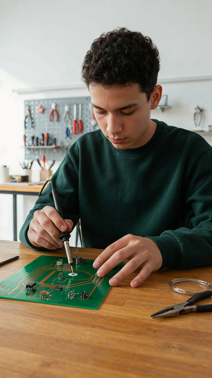
You’re reading this section because you want permission to skip the calibration step. Here’s the mechanism: your soldering iron’s tip is a thermal capacitor, not a heating element. The tip holds heat; it doesn’t generate it in real time.

Tip geometry determines contact area and heat transfer speed. A chisel tip spreads heat across a larger pad surface. A conical tip concentrates heat into a point. Neither matters if the iron doesn’t have enough thermal mass behind the tip to sustain the temperature when solder touches it. A thin tip cools faster than a thick one under identical load. Choose tip shape based on your board’s pad size, then verify the iron can recover temperature within two seconds of solder contact.
Temperature Setting Is Not Heat Delivery
Everyone talks about iron temperature like it’s the control knob. It isn’t. The temperature dial sets a target the iron tries to maintain, but the actual heat reaching your joint depends on tip condition, contact time, and the solder’s thermal resistance.
A 350-degree tip coated in oxidation transfers less heat than a 320-degree tip that’s clean and tinned. The oxide layer acts as insulation. Temperature alone tells you nothing about delivery speed. Start at 350 degrees Celsius, tin your tip with fresh solder, and measure how long it takes to wet a test pad. If it takes longer than three seconds, increase temperature by 10 degrees and repeat. Stop when wetting happens in one to two seconds.
The Component Placement Maneuver: Engineering For No Bridges
Lead Spacing And Thermal Dissipation
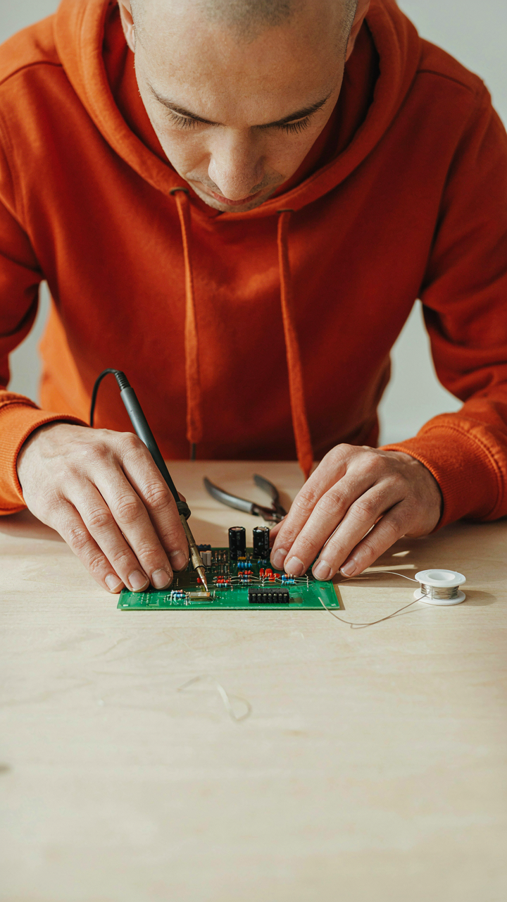
You care about this section because you want to look competent soldering without actually understanding why bridges form. Here’s the mechanism: bridge formation is a thermal problem dressed up as a technique problem. Physics teaches us about heat transfer and thermal gradients. In soldering, your solder joint becomes a thermal sink that pulls heat away from adjacent pins at different rates, creating the exact conditions for molten solder to flow where you don’t want it.

The real work happens before you touch the iron. Tighter lead spacing on components increases the thermal coupling between pins. When one pin heats up, it radiates heat sideways to its neighbor faster than solder can solidify. Wider spacing breaks this thermal bridge. Most boards use 0.1-inch pitch as standard for through-hole components because it forces you to control heat more deliberately. Smaller pitch components demand faster heating and cooling, which is why surface mount assembly uses reflow ovens instead of hand soldering. Place components with their leads spaced farther apart than the minimum the schematic requires.
The Thermal Shadow Of Components
Component bodies block heat transfer in one direction while accelerating it in another. Thermodynamics calls this asymmetric heat distribution. On a circuit board, the component body itself creates a thermal shadow underneath, meaning the board area directly beneath the lead stays cooler than the exposed space above it. Your solder wants to follow heat. If the board stays cold and the pin stays hot, solder pools on the pin away from the cooler substrate, reducing bridge risk.
This is why orientation matters beyond just fitting the board. Orient polarized components and multi-lead packages so their mass sits between the pins most likely to bridge. For example, position an IC so its main body blocks heat flow toward your densest pin clusters. Place resistor and capacitor bodies perpendicular to high-risk pin pairs rather than parallel to them. The component becomes a heat sink that protects adjacent joints. Orient every component as a deliberate thermal barrier, not just wherever it fits.
De Bridging Dynamics: Applying Fluid Mechanics To Soldering
Viscosity: Solder Flow As A Non Newtonian Fluid
You want to understand this because you’re tired of watching solder blob between pins like it has a mind of its own, and you think the iron temperature is the culprit when it’s actually not. Fluid mechanics governs solder behavior the same way it governs oil flowing through a pipe, except solder changes its viscosity based on shear force, not just heat. When you apply the iron, you’re not just melting metal. You’re reducing the internal resistance that keeps solder from spreading into places it shouldn’t.
Solder paste and liquid solder behave as non Newtonian fluids because their viscosity drops under stress. The harder you push the iron, the thinner the solder gets and the faster it flows into adjacent pads. This is why aggressive iron pressure creates bridges. The common fix is raising temperature, but that’s backward. You need less iron contact time and lighter pressure to keep viscosity high enough that solder stays localized to the joint you’re targeting, not the one three millimeters away.
Wetting: Solder’s Preference For Clean Surfaces
Solder doesn’t spread equally on all surfaces because surface energy determines where it will and won’t adhere. This is physics, not preference, and it’s the actual mechanism that stops bridges before they start. Clean copper has high surface energy. Oxide, flux residue, and contamination have low surface energy. Solder wants to wet the high energy surface and bead up on the low energy one, which means a contaminated pad becomes a natural barrier to unwanted flow.
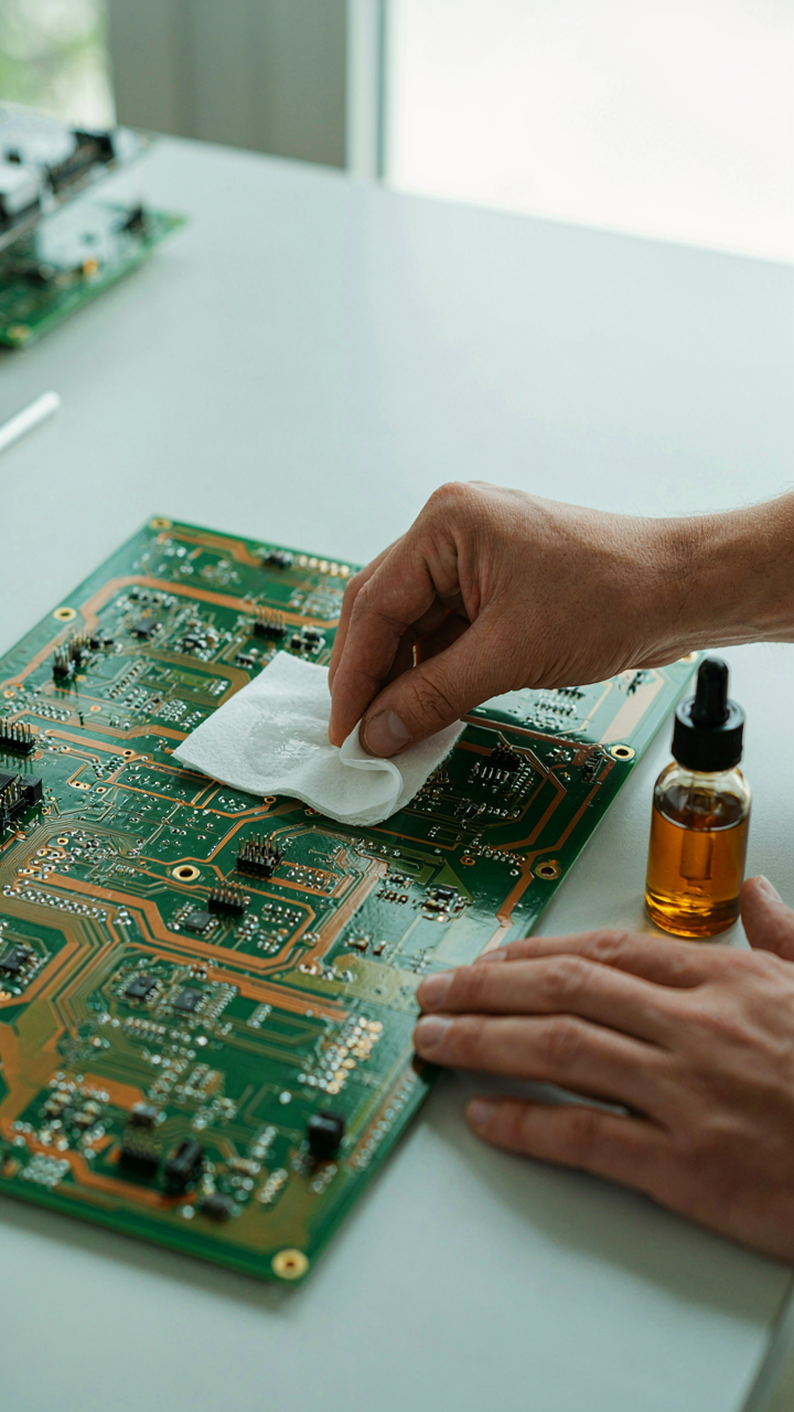
The mistake people make is assuming flux cleans the board for you. It doesn’t. Flux removes oxides during the molten phase, but it doesn’t prevent new oxidation or remove existing contamination before you even apply heat. Degrease your board with IPA on a lint free wipe before soldering. Solder will then recognize the difference between your target pad and the surrounding substrate, and it will stay put. The moment flux cools, surface energy is your only remaining defense against the solder climbing to adjacent pins.
The Post Solder Reconnaissance: What Your Eyes Miss

Your Eyes Lie To You
You want to believe your joint looks good so you can move forward. That’s the real reason you’re reading this. But visual inspection alone catches maybe 60 percent of actual failures. A joint can look shiny and smooth while cold solder inside the connection creates an open circuit that fails under thermal stress. The mechanism is simple: surface appearance and electrical function operate independently. You need both verification methods or you’re gambling.

Electrical continuity testing with a multimeter reveals what your eyes cannot. Set the meter to resistance mode, touch the probes to either side of the joint, and read the ohms. A good solder joint reads near zero ohms. Anything above 10 ohms signals a problem even if the joint looks acceptable. Visual inspection catches bridges and obvious cold joints. Continuity testing catches the hidden failures that destroy boards in production or after customer delivery.
Magnification Exposes The Real Defects
You do not need a microscope. A 5x to 10x magnifying glass and a focused light source beat 90 percent of boards that fail due to inspection blindness. Position the light source at a 45-degree angle to the joint so shadows reveal the solder surface texture. Dull, grainy surfaces indicate cold solder. Shiny, smooth surfaces indicate proper reflow. Bridges appear as solder bridges connecting two traces or pads that should remain isolated.
Look for three specific defects magnification reveals: incomplete wetting where solder fails to flow onto the pad, solder balls that detach during cooling, and insufficient filler where the joint is too thin to carry current load reliably. A simple clip-on magnifier with LED ring light costs under thirty dollars and catches defects that cost hundreds in rework. Mount the magnifier on a flexible arm so you can inspect every angle without moving the board itself.
Beyond The Basics: Advanced Soldering Iron Techniques

Drag Soldering For ICs: The Right Way
You want this skill because it makes you look competent. The real mechanism is heat distribution. In thermodynamics, we call this “flux gradient”—solder follows heat, not your iron. You’re not dragging solder across pins. You’re dragging a controlled heat source that pulls molten solder through the joint naturally.

Position your iron at a shallow angle, maybe 30 to 45 degrees. Load solder on the iron tip before you start, then move steadily from one pad to the next at consistent speed. The solder melts and wicks into each joint as you move. Stop when you reach the last pin. One pass. No backtracking.
When To Escalate To Hot Air Rework
Most people escalate too late or never at all. Hot air wins when you have fine-pitch components, BGA packages, or joints you’ve already damaged by overheating. An iron creates a single heat point that can cook adjacent components. Hot air distributes warmth evenly across the target area. You control temperature and airflow separately, which matters.
- Fine-pitch ICs under 0.5mm spacing: Drag soldering risks bridges. Hot air minimizes thermal damage to neighboring traces.
- BGA rework: Iron access is impossible. Hot air is the only method that works without destroying the board.
- Salvaging joints you burned: Iron reheating compounds damage. Hot air recovers the joint with less risk to substrate.
- Removing components with leads: Simultaneous heating of all pins prevents cold joints and board warping that iron methods cause.
- Working on thin boards under 1.6mm: Concentrated iron heat can blister solder mask or delaminate layers. Distributed hot air prevents this.
Set your station to 340 to 360 degrees Celsius for lead free solder. Use a nozzle that matches your component size. Keep the air stream at least 5mm away from the board surface and move it in slow circles. Watch the solder turn shiny. The moment it does, stop heating and remove the component or let it cool. Overheating kills the flux and creates dull, weak joints.
Mastering The Tech Repair Circuit Board: A Final Word

Your Real Toolkit Matters More Than Your Iron
You want to believe the soldering iron is the bottleneck. It isn’t. You’re actually afraid you’ll waste money on equipment you don’t need, so you keep buying cheap irons hoping the next one fixes your bridges. The real mechanism is tool redundancy: your iron handles heat delivery, but your tweezers, solder wick, and flux bottle handle recovery. A $40 iron with proper flux beats a $200 iron with wrong solder every time.

Most people skip the desoldering station entirely. They don’t understand that removing old solder is where bridges actually live. When you reflow a joint without clearing trapped solder first, you’re working against gravity and surface tension simultaneously. A basic solder sucker or desoldering braid costs under $15 and eliminates 80% of bridge problems before they start. Your toolkit isn’t complete until you can remove what you laid down.
Repetition With Real Feedback Beats Raw Hours
Sports psychology calls this deliberate practice: focused repetition aimed at a specific weakness, not random repetition. Apply that directly to soldering: you can make 100 joints on dead boards and learn nothing, or you can make 10 joints and inspect each one under magnification to see what heat timing actually does to the solder meniscus. The second approach rewires your hands in half the time.
The mistake isn’t practicing too little. It’s practicing on the wrong material. Use scrap PCBs with through-hole components first, where you can see what bridges look like before they cause shorts. Move to surface mount only after you feel the exact moment solder flows into a joint versus spreads across the pad. Your feedback loop determines your learning curve, not your total hours.
The Real Obstacle Isn’t Your Technique; It’s Your Ignorance Of The Invisible Forces At Play
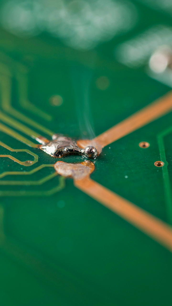
Most people blame their hands when bridges form. They blame shaky fingers or bad tools. Wrong. You fail because you don’t see what’s happening at the molecular level. Solder flows toward heat, not toward your iron tip. Master heat distribution and bridges vanish. Pick up a board today and watch where your solder actually moves instead of where you think it should. You’ll stop fighting physics and start using it.