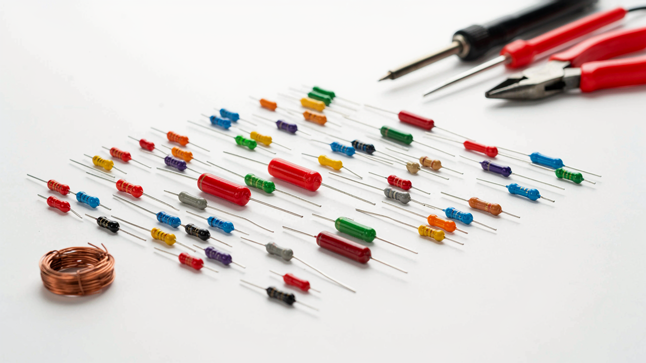
The Illusion Of Complexity: Why Most Resistor Color Code Guides Fail
Memorization Doesn’t Build Understanding
You want to skip the work of actually learning this so you can feel competent fast. The trap most guides set is turning the color code into a rigid memorization task instead of showing you the system underneath. Memorization creates dependency. You forget the sequence, you’re stuck. Understanding the sequence means you rebuild it from first principles whenever you need it, even years later.
The resistor color code isn’t arbitrary. It uses the visible spectrum in order: black, brown, red, orange, yellow, green, blue, violet, grey, white. This isn’t a mnemonic you force into your brain. It’s a pattern. Digits zero through nine map to these colors in sequence. Once you see that, the “difficulty” evaporates. You’re not memorizing. You’re recognizing.
The System Beyond The Chart
Most beginner guides show you a color chart and call it done. That’s incomplete. Here’s what they skip: the color code solves a physical problem. Resistors are tiny. Printing tiny text on them fails. Colors stay legible when ink degrades or components age. The code is a durability solution dressed as a standard.
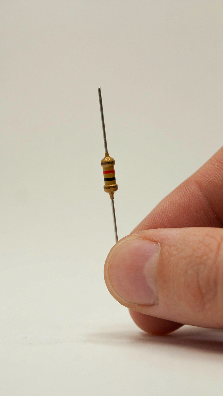
The actual reading mechanism matters more than the chart. You hold a resistor with the tolerance band on the right. You read left to right. The first two bands are digits. The third band is the multiplier, the power of ten. The fourth band is tolerance. This sequence isn’t random instruction. It’s built so you physically can’t misread it if you follow the protocol. Master the protocol, not the memorization.
The Ohm’s Law Analogy: Understanding Resistor Value
Resistance As A Flow Regulator
You want to decode colors fast so you feel competent without actually building anything. Here’s the mechanism that matters: think of resistance like hydraulics. In fluid dynamics, a valve controls flow rate by creating pressure drop. A resistor does the exact same thing to electrical current. The color bands tell you how tight that valve is. Tighter valve, higher resistance value, less current flows. The bands are just the language that number gets encoded into.

Value isn’t abstract. A resistor blocks current proportionally to its resistance measured in ohms. The color code translates that number into a visual you can read before soldering. Without it, you’d need to measure every resistor with a meter first. The bands save time on the build. They’re a practical indexing system, nothing more mystical than that.
Why The Right Value Stops Your Circuit From Failing
Most beginners think resistor value is negotiable. It’s not. The wrong value either starves your component of current or fries it. In a simple LED circuit, pick a resistor too low and the LED burns out in seconds. Pick one too high and the LED stays dark. The color code determines which outcome happens. This is why reading the bands correctly isn’t optional learning, it’s mandatory circuit literacy.
The mechanism is direct: voltage stays constant, but current changes based on resistance according to Ohm’s Law. Your power source has a fixed voltage. The resistor value controls how much current that voltage pushes through. When you decode the color bands correctly, you get the exact restriction your circuit needs. When you misread them, your circuit either fails silently or violently. Read the bands left to right, match each color to its digit on the standard chart, combine them, and you have your ohm value. That’s the protocol.
The Four Band Protocol: Deciphering The Core

First Two Bands: Reading The Base Value
You want to decode a resistor fast so you look competent and don’t waste time squinting at tiny stripes. The mechanism is simple: the first two bands give you the significant digits of the resistance value. Nothing more. The first band is the tens place. The second band is the ones place. You stack them left to right. That’s it.

The color chart maps to numbers zero through nine. Black is zero, brown is one, red is two, and so on up to violet at nine. The bands sit in a specific order on the resistor body, and manufacturers always print them closer to one end. Find that end, read left to right, grab your first two digits, and write them down as a two digit number before you touch the third band.
The Multiplier: Power Of Ten
Think of the multiplier band like an exponent in mathematics. The first two bands gave you a base number. The third band tells you what power of ten to multiply that base by. Brown means times ten to the first power. Red means times ten to the second power. This is where people get confused because they skip the naming step and try to do it all at once.
Your two digit number from bands one and two multiplies by ten raised to whatever power the third band represents. Black multiplies by one (ten to the zero). Gold multiplies by point one (ten to the negative one). Silver multiplies by point zero one (ten to the negative two). Read the third band, identify the multiplier value, apply it to your base number, and you have the resistance in ohms.
Tolerance: The Unsung Hero Of Reliability
What That Fourth Band Actually Means
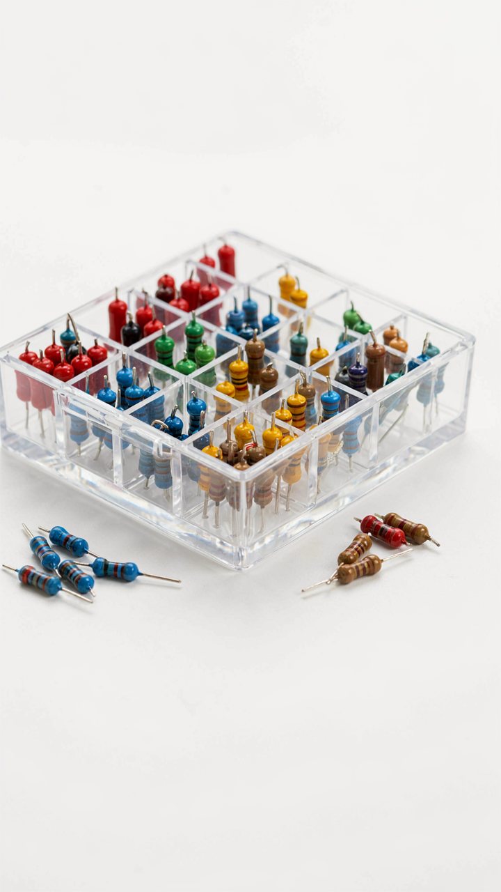
You want to know the tolerance band because you’re afraid your circuit will fail and you won’t know why. Here’s the mechanism: the fourth band tells you the acceptable deviation from the marked resistance value as a percentage. A resistor marked 1000 ohms with a 5% tolerance can legally measure anywhere from 950 to 1050 ohms and still be within spec. Manufacturers build this wiggle room in because perfect resistance doesn’t exist in the physical world.

The tolerance band uses specific color codes tied to percentage ranges. Gold means 5%, silver means 10%, and brown means 1%. Higher precision requires tighter tolerance, which costs more to manufacture and verify. You pick a tolerance based on what your circuit demands, not based on what sounds safer. A 10% resistor works fine in most amplifier biasing circuits. A 1% resistor matters when you’re building precision measurement equipment or audio crossovers where frequency response depends on exact resistance values.
Where Tolerance Actually Affects Circuit Behavior
Think of tolerance like variance in systems theory: the measure of how much a component can drift and still perform its intended function. A circuit designed with 5% tolerance resistors will behave predictably across those acceptable deviations. A circuit designed with 10% tolerance resistors might drift outside specification if multiple resistors all stack toward their limit in the same direction. Tolerance compounds when resistors work together, especially in voltage dividers or filter networks where precise ratios matter more than individual values.
Aging and temperature also shift resistance over time, and tolerance doesn’t protect against that. A resistor at the edge of its tolerance band today might drift further tomorrow. You must account for both the initial tolerance and the expected drift when selecting components for long-term applications. If you need a circuit that stays stable for years, start with tighter tolerance and account for drift in your design margin, not just in the color code selection.
Beyond Four Bands: Precision And Specialty Resistors

Five And Six Band Codes Add Real Accuracy
You want to believe a four-band resistor is “good enough” because you don’t want to learn more. It isn’t. A five-band resistor adds a third significant digit, cutting tolerance in half. The first three bands show value. The fourth band shows multiplier. The fifth band shows tolerance, usually 1% or 0.5%. This matters when you’re building audio circuits, measurement gear, or anything where drift kills performance.

Six-band resistors go further. They add temperature coefficient as a sixth band, telling you how much the resistance drifts as heat changes. This band uses a color code separate from the tolerance system. Temperature coefficient matters in precision instruments, industrial controls, and RF circuits where thermal stability determines whether your design works or fails.
Temperature Coefficient Separates Good From Mediocre
Thermal management from physics teaches you one principle: every material responds to temperature change. Apply that to resistors. The temperature coefficient (ppm/K) tells you resistance change per million parts per resistor per degree Kelvin. A 1% tolerance resistor with a 100 ppm/K coefficient will drift 0.1% for every 10-degree temperature swing. Most makers skip this detail because most designs don’t need it. Your design might.
The sixth band uses a distinct color order tied to specific ppm/K values. Brown is 100 ppm/K. Red is 50. Yellow is 25. Specialty resistor datasheets state these explicitly. You read the sixth band the same way you read the first five, but the result isn’t a tolerance range. It’s a temperature behavior guarantee. When you need stability across a wide operating range, this band separates resistors that perform from resistors that drift out of spec.
SMD Resistors: When Bands Disappear
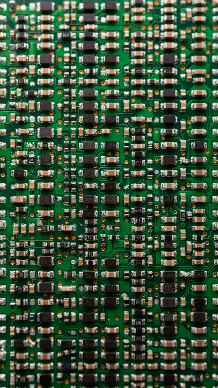
Reading Numbers Instead Of Colors
You’re learning color codes because you want to feel competent working with electronics, but SMD resistors expose that those bands were always a crutch. Surface mount resistors use a code system borrowed from chemistry and mathematics: the three-digit marking replaces the five-band system with pure notation. The first two digits represent significant figures, and the third digit is the multiplier as a power of ten, identical to how chemists notate concentration values.

SMD resistor codes appear as stamped numbers on the component body. A marking of 470 means 47 × 10 to the first power, which is 470 ohms. A marking of 104 means 10 × 10 to the fourth power, which is 100,000 ohms or 100k. The system is faster to print and read than color bands because it removes ambiguity. You decode it the same way every time, with no lighting conditions, no color blindness complications, no squinting at a tiny component.
Identifying Resistors Without Guessing
Most beginners skip this step entirely and just test components with a multimeter, which wastes time on components you already know the value of. Start by understanding that SMD resistor sizes follow a standard naming convention: 0603, 0805, 1206. These dimensions represent length and width in hundredths of an inch, not the actual resistance value. The marking printed on the resistor is your only source of truth.
Use a multimeter or component tester as your verification step, not your primary identification method. Read the printed code first, then test to confirm. This trains your ability to recognize patterns and builds speed. On older or worn boards, markings fade. When they do, measurement becomes your only option, but treating the meter as your starting point wastes your attention on work the marking already did.
The Resistor Color Code Guide: Your Brain, Not A Chart

Speed Reading Bands Before You Need Them
You want to look competent without actually memorizing anything. Here’s the mechanism: your brain stores patterns faster than facts. The resistor color code isn’t a chart to memorize—it’s a sequence your eyes learn to recognize in real time, the way you read words without sounding out letters.

Start with high-frequency resistor values. Build a visual library by handling actual components. Every time you see a brown-black-red band sequence, your brain tightens the association to 1000 ohms. Repetition collapses the gap between reading and knowing. Speed comes from exposure, not effort.
- Brown-Black-Red: 1000 ohms. The most common resistor value in beginner circuits. Lock this pattern first before moving to variations.
- Brown-Black-Brown: 100 ohms. Appears constantly in LED current-limiting and sensor circuits. Train your eyes to see this three times daily minimum.
- Brown-Red-Red: 1200 ohms. A standard value for audio and signal processing. Less common than 1K, but worth building recognition early.
- Yellow-Violet-Red: 4700 ohms. High-value resistor for pull-up and pull-down logic. The yellow start makes it distinctive in circuits.
- Red-Red-Red: 2200 ohms. Sits between common values. Your brain needs this as a bridge pattern to avoid misreading sequences.
The color code exists because manufacturing needed a readable label during assembly. Bands wrap around the body where print couldn’t grip reliably. Once you’ve physically sorted ten resistors by value, you won’t need a reference card again.
The Pattern Your Brain Already Knows
Forget the generic “use a rhyme device” advice—that wastes mental energy on external memory when your brain prefers visual shortcuts. Take the mnemonic route if you want, but the real lever is mapping color to numeric position. Black is always zero. Brown is always one. This position rule cuts the learning surface in half.
Your brain already tracks position hierarchies—it’s how you read numbered lists without conscious effort. Apply that same mechanism here. The first band tells magnitude. The second band refines it. The third band multiplies by powers of ten. Once you internalize that the multiplier band follows a predictable scale, you stop decoding and start recognizing instantly.
Real World Application: Where The Rubber Meets The Road

Troubleshooting Circuits Using Color Codes
You want to look competent when a circuit fails. The real mechanism is this: color codes let you verify resistance without power, which means you isolate problems before they cascade. Most people read colors wrong because they rush or misidentify the band order. Start from the end closest to the edge of the resistor. Hold it so the tolerance band sits on your right. Read left to right from there. The first two bands are digits. The third is the multiplier. The fourth is tolerance.

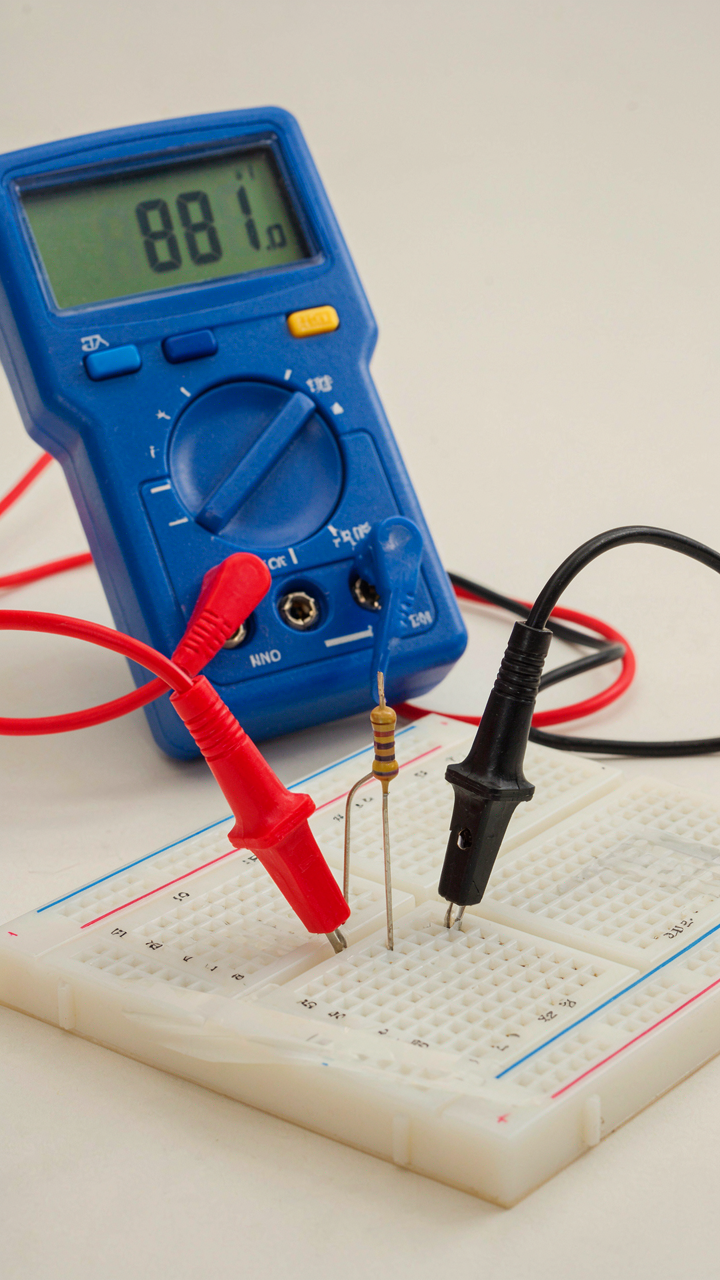
When a circuit misbehaves, resistance drift is your first suspect. Measure the resistor’s actual value with a multimeter in ohms mode. Compare it to what the color bands promise. If they match, the resistor is good. If they diverge by more than the tolerance band allows, replace it. This eliminates a variable before you chase voltage or continuity problems elsewhere. You save hours by checking components in isolation first.
When Color Codes Lie To You
The common advice says “just memorize the rainbow mnemonic.” That’s incomplete. The real problem is band ordering and bad light. Resistors sit on circuit boards under glare. Colors compress and blur. Brown and red look identical under fluorescent lights. The tolerance band confusion kills most people: they read it as data when it’s actually permission for error. A resistor labeled with 5 percent tolerance can drift that far and still be “correct.”
Here’s what actually works: physical confirmation beats color reading every time. If you cannot read the bands clearly, do not guess. Take a photo under bright, diffuse light. Use a magnifier if needed. Cross reference with a multimeter measurement. Never rely on color codes alone for critical circuits. The chart printable approach is marketing. The mechanism that matters is this: resistors age, drift, and burn. Their color bands fade. Measure. Verify. Move forward.
Beyond The Resistor: Other Wiring Codes
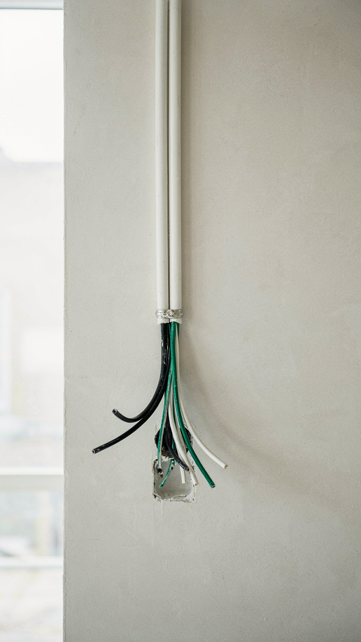
The Real Electrical Wiring Standards
You’re reading this section because you want to feel like you understand the whole system, not just one piece of it. Here’s the mechanism: resistor color codes are a component-level language, but buildings and power systems run on a completely different wiring language. The standards diverge because scale matters. A resistor sits on a circuit board where space is tight and stakes are low. Electrical wiring in walls carries lethal current and needs standardized colors so any electrician anywhere can identify what they’re touching.

The color standards for building wiring emerged from practical necessity, not design. Each color carries a specific function: black and red for hot conductors, white for neutral, green or bare copper for ground. These codes developed regionally first, then standardized through organizations like the National Electrical Code in North America and IEC standards internationally. The resistor color code predates modern electrical wiring standards by decades, which is why they use completely different logic and why confusing them will cause real problems.
Where These Codes Actually Matter
The distinction cuts sharply: resistor color codes tell you component values in circuits. Wiring color codes tell you electrical safety in buildings and large systems. Never mistake one for the other. Wiring codes apply anywhere AC or DC power distributes through fixed installations: residential homes, commercial buildings, industrial plants, and vehicle harnesses. They also govern temporary installations, extension cords, and any permanent circuit where a human could touch a conductor and die.
Resistor color codes stay confined to schematic diagrams, circuit boards, and component selection. Once you leave the PCB level, color coding switches to a safety framework entirely. An electrician pulling wire through conduit follows wiring standards. A technician replacing components on a board follows resistor codes. The application determines the language. If you’re designing circuits on a breadboard or reading schematics, resistor color codes are your tool. If you’re installing anything that connects to mains power or permanent infrastructure, wiring codes are your legal and safety requirement.
The Real Obstacle Isn’t The Code; It’s Your Addiction To Overcomplication And The Belief That Mastery Is Achieved Through Charts, Not Action

You memorized nothing from this article and you don’t need to. Grab a resistor today, look at the bands, and decode it using what you learned. That’s it. Your brain locks patterns through doing, not reading. Everyone fails the first time. Everyone gets it the second. Stop treating resistor codes like a test you study for and start treating them like a tool you use. Mastery isn’t a destination you arrive at after enough preparation; it’s a side effect of getting your hands dirty.