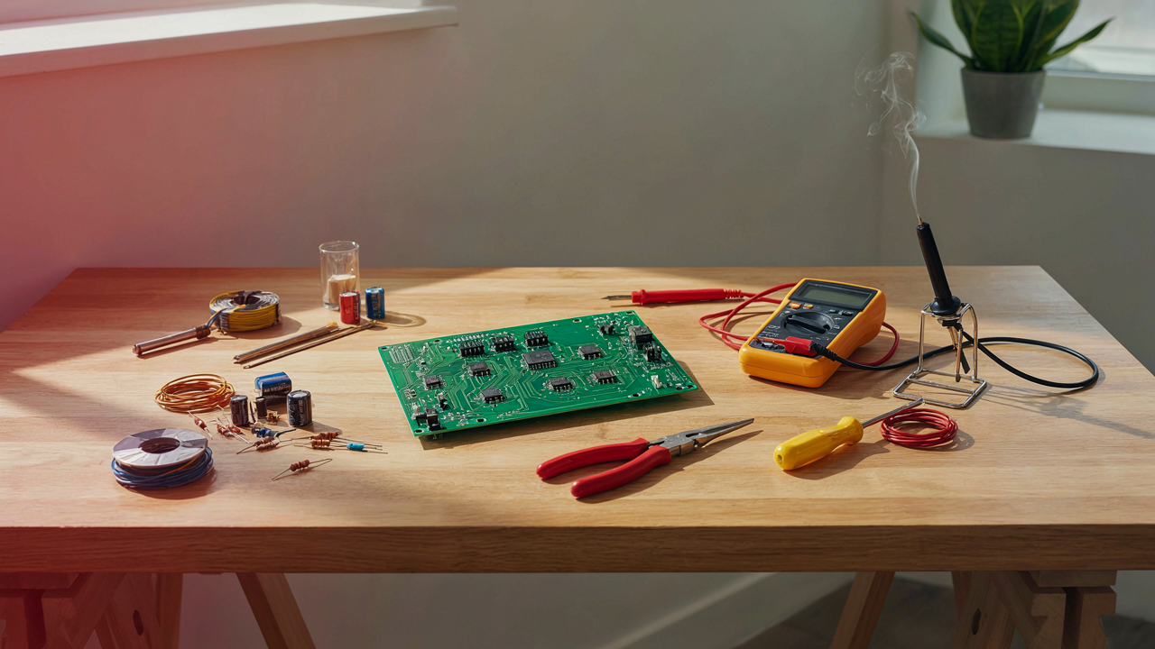
The “Utility First” Mandate For Electronic DIY Projects

Start With A Problem You Actually Have
You want a hobby that feels productive because you’re afraid of wasting time on something frivolous. Here’s the mechanism: the best electronics projects solve a friction point you encounter repeatedly, not a theoretical problem you invented to justify tinkering. Boredom kills projects faster than difficulty does. Pick something that interrupts your actual life at least twice a week. A broken lamp you’ve ignored for months. A thermostat that doesn’t read accurately. A speaker system that never powers off cleanly.
The constraint is the engine. When you build something to fix a real annoyance, you have a built-in feedback loop. You use it immediately. You notice what fails. You iterate without needing motivation. This beats starting with a breadboard and a vague idea about “learning Arduino.” The project owns you instead of the other way around.
Build Toward Output, Not Complexity
Skip the common advice that says “start simple.” That’s lazy guidance. Start specific. Your project needs a tangible, measurable outcome: a device that does one thing reliably, not a collection of components that light up. A moisture sensor that texts you when a plant needs water. A timer that kills power to standby devices. A light that dims based on ambient brightness. Output first, bells and whistles never.
The trap is treating the learning as the goal. It’s not. The learning is the cost you pay to get a result. Design backward from that result. What does success look like in your home or workspace? What stops working now that would work better? That clarity collapses the scope and forces you to make real engineering trade-offs instead of following a tutorial that teaches nothing about decision-making.
Escape Tutorial Traps: True Electronic Project Mastery

Take Apart Something That Works
You want the shortcut to competence without admitting you’re scared of breaking something expensive. The real mechanism is this: tutorials teach you theory in isolation, but working devices teach you constraint. In systems thinking, constraint is how you map dependencies. Take apart a dead laptop, old phone, or broken microwave. You see how engineers route power, how they group components by function, how they manage heat. You learn why they chose those specific values for resistors and capacitors, not because someone told you the math, but because you can trace the outcome through the circuit board itself.

The gap between building from a schematic and reverse-engineering a real device is the gap between understanding rules and understanding why rules exist. When you extract a power management IC from a circuit board, you’re not just learning what it does in theory. You’re seeing how it connects to everything else, what protection circuits surround it, which pins matter for your specific use case. This is the work that tutorials skip because they can’t fit it into a step-by-step format. Spend a rainy weekend pulling apart three devices you no longer use. Document the layout. Trace one subsystem completely before moving to the next.
Map The Signal Path, Not Just The Schematic
Most hobbyists read a schematic like it’s a map with equal roads everywhere. It’s not. Power supply circuits, signal paths, and protection circuits are separate hierarchies that overlap. Think of it like topology from mathematics: what matters is which node connects to which, not the physical distance. Identify where power enters the device. Follow it to every major component. Then trace the signal that actually does the work, separate from the support systems around it. A microcontroller doesn’t exist alone; it needs a clock source, voltage regulation, and a reset circuit. That’s three functional blocks, not one component.
The real education happens when you stop seeing a schematic as “the thing” and start seeing it as a visual map of how one block talks to another. Find a device schematic online for something you’ve taken apart. Overlay what you actually see on the board against what the schematic claims. Notice where manufacturers simplify the schematic for clarity, where they add components the schematic doesn’t show, where cost optimization actually changed the design. This is how you learn to read between the lines of engineering decisions. Grab a device you still have access to, pull the schematic from the manufacturer, and mark up the power and signal paths with different colored markers on a printout.
The Constraint Led Innovation Protocol For Electrical Engineering Projects
Set Hard Boundaries Before You Start
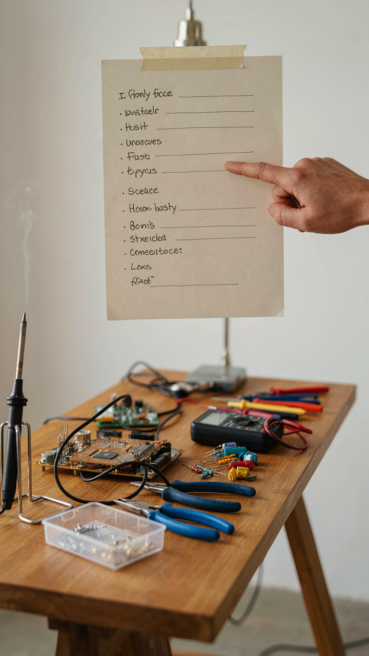
You’re drawn to this because you suspect unlimited options paralyze you, and you’re right. Constraint-led innovation comes from systems design: the principle that friction forces elegance. Before breadboarding anything, declare your material budget, time box, and component count. A Saturday project means eight hours maximum. A five-dollar parts limit means no premium modules. A ten-component ceiling means ruthless prioritization. These walls aren’t limitations. They’re the scaffolding that forces trade-off decisions you’d otherwise avoid by overthinking.

The mechanism works because scarcity triggers pattern recognition. Your brain doesn’t waste cycles on ten thousand possible solutions when it has four hours and three dollars. It cuts straight to the core function. Hobbyists who ignore this boundary-setting phase drift into expensive, half-finished projects. Start by writing constraints down. Time limit. Budget. Parts available. Component count. Then build to those edges, not against them.
The Problem Solving Emerges From Friction
Most hobby advice says pick a project first, then gather parts. That’s backwards and wastes weekends. Reverse engineer the constraint: take your material ceiling and ask what problems that specific collection solves. You have old phone chargers, a broken remote, a handful of resistors, and four hours. What can those parts do together? This friction between available resources and possible outcomes generates novelty. Necessity creates circuit topology you wouldn’t have designed on a blank slate.
The real work happens in the gap between what you want to build and what your constraints allow. Can you blink an LED with salvaged components instead of a dedicated IC? Can you measure voltage with a photodiode and a phone camera instead of a multimeter? These constraints force you into first-principles thinking. You stop following tutorials and start becoming an engineer. Spend your first hour mapping what you have, your second hour listing what it could do, and your remaining hours executing the best collision between the two.
Beyond Blink: Arduino Uno Projects With Real World Interfacing
Reading Temperature And Humidity From The Air Around You
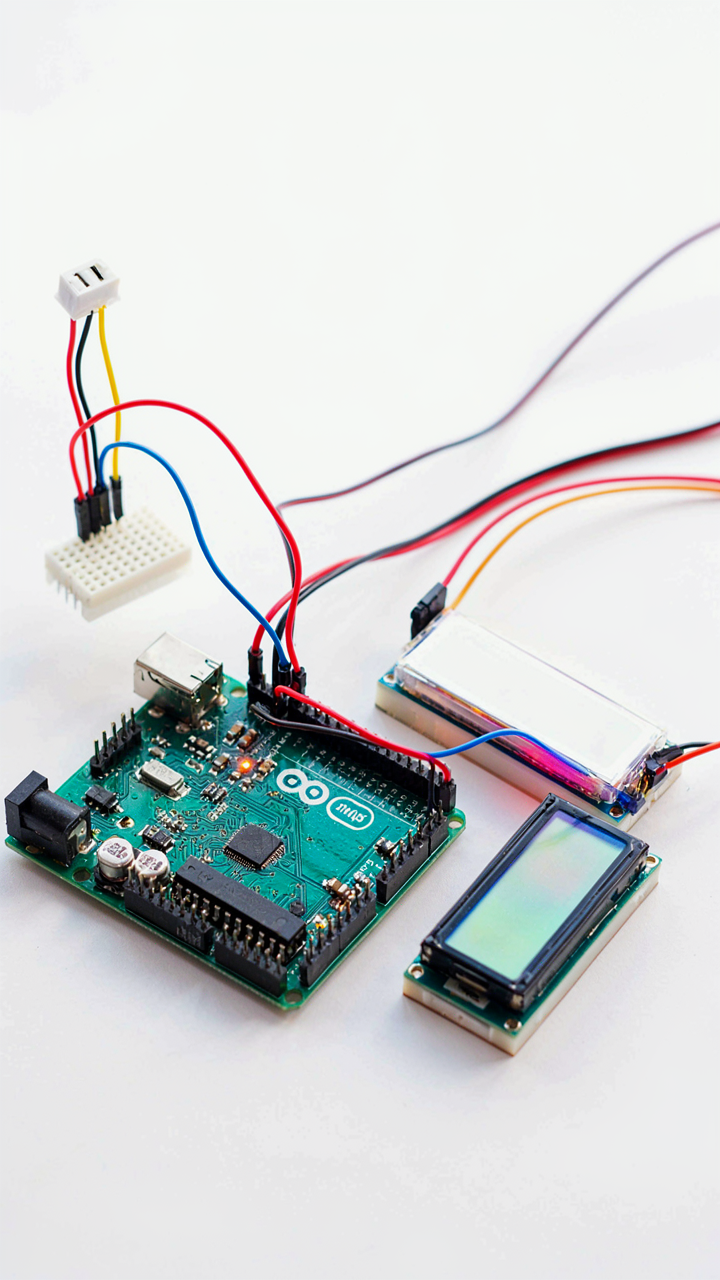
You want to feel like you’re building something real instead of just making an LED flash on command. The mechanism is feedback: sensors transform the invisible into data your Arduino can read, process, and react to. Temperature and humidity sensors like the DHT22 connect to a single digital pin and return two usable measurements in under a second. The Arduino reads the signal, parses it, and you get actionable numbers instead of guessing.

Start with a DHT22 wired to pin 2, ground, and 5V. Download the DHT library from Adafruit, upload their example sketch, open the serial monitor at 9600 baud, and watch live readings appear every two seconds. No calibration required. The sensor costs under five dollars. Connect an LCD screen to display the data on a physical display instead of just a computer window, and you’ve built an environmental monitor that actually sits on a shelf and works.
Controlling Motors, Lights, And Relays With Direct Commands
Most tutorials tell you actuators are just “outputs you can control.” Wrong. Actuators are load switching mechanisms, borrowed from control systems engineering. Your Arduino’s pins output 40 milliamps maximum, which can’t drive a motor or heavy relay directly. You need a transistor or relay module that accepts the Arduino’s low signal and switches the high current load separately. This is the real mechanism nobody emphasizes.
A relay module rated for 5V logic input and 10+ amp output costs three dollars and eliminates the guesswork. Connect your Arduino pin to the relay input, ground to ground, and 5V to 5V. The relay then switches your motor, pump, or lamp on a separate circuit with its own power supply. Upload digitalWrite commands to pin 3, test with a simple sketch that toggles the relay every three seconds, and the motor turns on and off on demand. No magic involved. Just signal, switching, and current separation working as intended.
Systems Thinking For Tech Project Ideas: From Cells To Circuits
Redundancy Beats Single Points Of Failure
You want to feel like you’re building something robust. The actual reason you care is avoiding the moment a single bad component kills your whole project. Biology solved this problem millions of years ago through redundancy, and circuits that copy this principle survive neglect and mistakes.

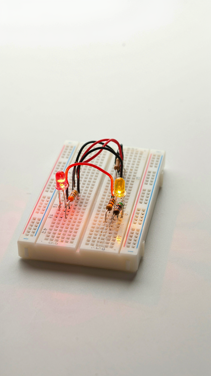
Biological systems don’t collapse when one cell dies because backup pathways exist everywhere. In electronics, this translates to parallel branches instead of series chains. A LED indicator circuit with one resistor dies if that resistor fails or gets miscalculated. The same circuit with two parallel indicator paths keeps working even if one path opens. You’re not adding complexity for status. You’re engineering reliability into the foundation.
Most hobby builds fail during testing because they assume perfect conditions. They don’t. The moment you power on a new circuit, voltage spikes, thermal stress, and tolerance drift hit simultaneously. Building in intentional redundancy means your circuit still functions when reality doesn’t match the schematic. Add a bypass capacitor in parallel with your main capacitor. Include a secondary ground plane. Run critical signal lines with traces you could trace with your eyes closed. The mechanism is simple: design so the failure of any single component doesn’t cascade into total failure.
Feedback Loops Shape Circuit Behavior
Cybernetics is the study of control and communication in systems. A feedback loop in a circuit does exactly what it does in an organization: it measures output, compares it to a target, then adjusts the input to close the gap. Most hobby builders ignore this entirely, then wonder why their circuits drift or oscillate unpredictably.
A basic LED dimmer circuit without feedback is just a resistor. Brightness depends entirely on power supply voltage. If your supply drifts from 5V to 5.5V, brightness changes without you touching anything. The same circuit with negative feedback (using an op-amp or comparator to sense brightness and adjust current) holds output constant regardless of input variation. Audio amplifiers, temperature controllers, and power regulators all use this same mechanism to stay stable. The feedback loop measures the actual output, compares it to your target, and corrects automatically.
Positive feedback amplifies change. Negative feedback dampens it. Most useful hobby circuits need negative feedback because you want predictable, stable behavior. When you build a circuit that oscillates or drifts wildly, you’re looking at either missing feedback or feedback fighting against itself. Install a feedback network that senses your output, feeds that information back into your control stage, and lets the circuit self-correct. This is how precision happens in electronics without constantly tweaking components by hand.

Deconstructing Complexity: Engineering Projects Ideas, Not Just Assembly
Break Your Vision Into Functional Blocks
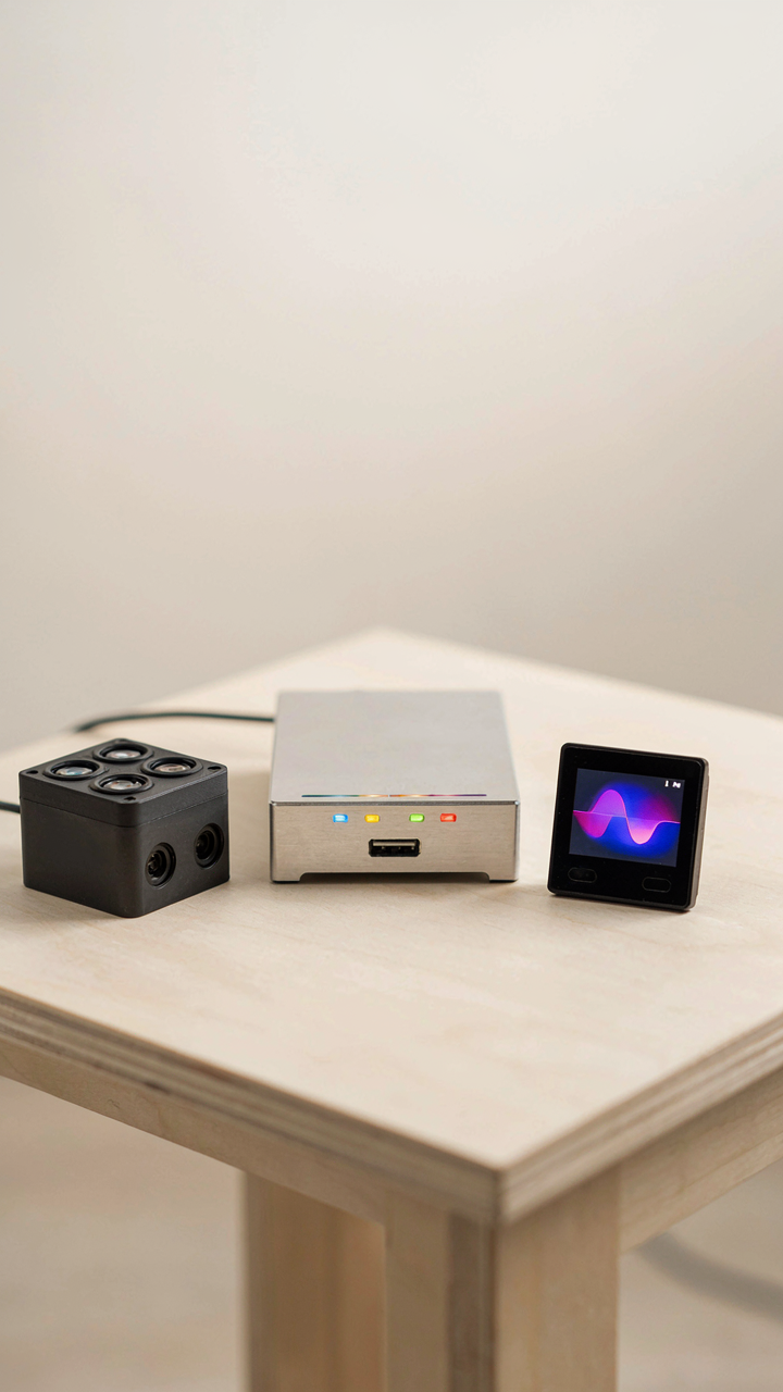
You want to feel like an engineer, not a parts assembler, and that requires actually understanding what you’re building. The real mechanism here comes from systems engineering: decomposition. In electronics, this means treating your project as separate, testable subsystems instead of one monolithic black box. A weather station isn’t one project. It’s a sensor module, a data logger, a display interface, and a power system. Each one solves a distinct problem.
Most hobby guides gloss past this and hand you a schematic. That’s garbage advice. You’ll build it, it won’t work, and you’ll blame yourself instead of the approach. Start by defining what each subsystem does in one sentence. The sensor reads humidity. The microcontroller processes it. The display shows it. Test each one independently before connecting them. This is how real engineers work, and it’s the only way a rainy weekend project doesn’t turn into debugging hell.
Master One Subsystem Before Integration
Don’t touch integration until you’ve owned the hardest part first. Pick the subsystem that scares you most and build it standalone, with temporary power, temporary outputs, temporary everything. If your project involves analog signal conditioning, master that circuit on a breadboard with a function generator and oscilloscope before you worry about the microcontroller reading it.
The reason this works is psychological and practical. You build confidence on real results. You learn what actually breaks and why. You create a proven building block you can trust later. Once one subsystem works reliably in isolation, adding the next one becomes a controlled experiment, not a disaster investigation. The integration phase becomes boring, which is exactly when you know you’ve done the prep work right.

The “Failure As Feedback” Loop For Electronics Projects For Beginners
Write Down What Broke And Why
You want to feel like you’re making progress without actually having to change anything. That’s the real reason most people skip documenting failures. The mechanism is simple: your brain forgets what didn’t work, so you repeat the same mistake three weeks later and call it a new problem. Borrowed from systems engineering, this is signal versus noise. You need to separate which component actually failed from the conditions that preceded it.
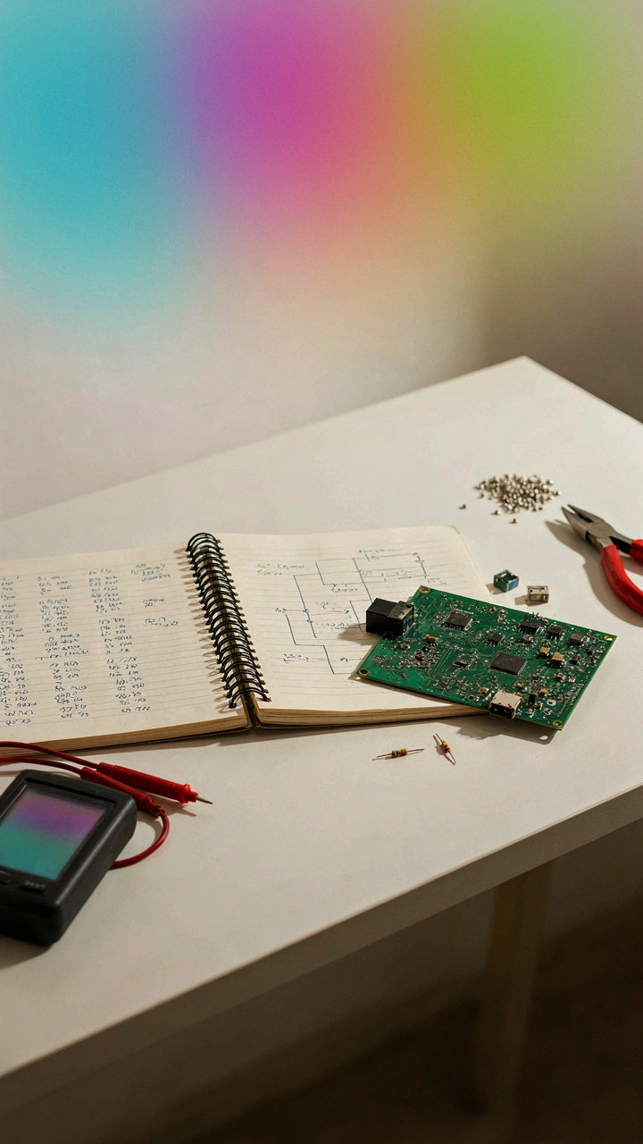
Keep a physical notebook next to your workbench. Record the circuit configuration, the component values you used, what happened when power went on, and what temperature or voltage reading you got before it failed. Don’t write “LED didn’t light up.” Write “5V across 330 ohm resistor to LED anode, LED cathode to ground via resistor to pin 3 of ATmega328. No voltage drop across LED when measured with multimeter. LED tested separately and worked.” That specificity is the only data that matters.
Measure, Change One Variable, Repeat
This is where most beginners fail. They assume iteration means “try a bunch of stuff and see what sticks.” That’s cargo cult engineering. Real iteration means changing one element at a time while holding everything else constant, then measuring the result before moving forward.
- Resistor value swaps: Replace one resistor in the circuit while keeping all others identical. Measure the output voltage or current. Document the before and after readings.
- Component substitution: If a transistor didn’t switch properly, try a different part number from the same family while using the same resistor values and circuit layout.
- Voltage supply changes: Test the circuit at 3.3V, then 5V, then 9V without modifying any component values. Record the performance at each level.
- Layout modifications: Move a wire, shorten a trace on a breadboard, or relocate a capacitor closer to the power pin. Run the same test again and check for noise reduction or stability gain.
- Timing adjustments: For projects with delays or PWM signals, change the frequency or pulse width by one step, measure the effect, then adjust again based on results.
Empirical results are the only language electronics speaks. Your circuit doesn’t care what you intended. It responds to what you built. Change one thing, measure what changed, then decide your next move based on data, not assumption. This is how you move from random tinkering to actual design skill.

Monetize Your Mind: Turning Electronic Project Ideas Into Value

Find Problems People Actually Pay For
You want permission to feel like your hobby matters. Here’s the mechanism: most hobbyists build what interests them, not what solves friction in someone else’s workflow. Economics calls this the difference between supply-push and demand-pull. In electronics, demand-pull means you spot a repeated complaint in a specific community, then engineer toward that gap instead of hoping someone wants your creation.
Niche problems have two markers. First, the person experiencing them already spends money trying to solve them badly. Second, they’re specific enough that generic solutions don’t fit. A maker complaining about unreliable temperature sensors in their reflow oven has a problem. A vague desire for “better Arduino projects” does not. Talk to people in maker spaces, repair communities, and industrial settings. Listen for the word “wish” followed by a technical complaint.
Validate Before You Build The Whole Thing
The common advice here is wrong: most people don’t need a finished product to test market fit. You need evidence that someone will exchange money for the solution, and you need it before you invest time in design refinement. This means a non-functional prototype or a written specification can trigger a real purchase commitment from a real buyer.
Build the minimum viable product as a proof mechanism, not a sellable unit. Show a working breadboard version, a 3D-printed enclosure with dummy internals, or a detailed spec sheet with pricing. Ask directly: would you buy this for this price if it shipped in four weeks? Record yes or no. Five genuine yeses from separate buyers is your signal to optimize for production. One person saying “that’s cool” and walking away teaches you nothing about market reality.

The Real Obstacle Isn’t Lack Of Ideas, But The Fear Of Committing To Genuine Skill Acquisition

You already know what electronics project excites you. The real problem is you’re treating hobbies like Netflix subscriptions instead of skills worth developing. Pick one project today and commit to finishing it, even if it takes three weekends instead of one. The hobbyists who actually build things aren’t smarter than you. They just refused to let boredom kill momentum before mastery started. Stop researching kits and start soldering.