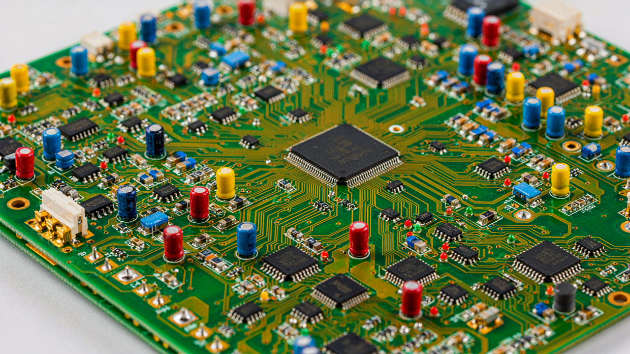
The Myth Of Intuitive Reading: Why Your Brain Fails Early

Symbols Are Instructions, Not Pictures
You want to feel smart fast. That’s why circuit diagrams intimidate you—they look like they should make sense instantly, and when they don’t, you assume the problem is you. It isn’t. The real mechanism at work here is semantic mismatch. Your brain tries to read a circuit diagram the way it reads a photograph, extracting visual meaning through shape recognition. It fails because diagrams aren’t representations of reality; they’re encoded instructions. A resistor symbol isn’t what a resistor looks like. It’s a visual token that means “this component opposes current flow.”
The moment you stop hunting for visual realism, everything shifts. A battery symbol showing two lines of different lengths doesn’t picture a battery. Those lines encode information: which terminal is positive, which is negative, what the voltage is relative to other components. The diagram speaks in abstraction because abstraction compresses information. You’re not looking at a picture. You’re decoding a language someone designed specifically to be written and read by engineers without ambiguity.
Abstraction Is The Only Way Information Scales
Common advice tells you to “start simple” or “memorize the symbols.” That’s lazy. The real reason abstraction works in circuit diagrams comes from information theory—the field that measures how much data you can pack into a limited space without corruption. A realistic drawing of a resistor occupies ten times more space than its symbol but contains zero additional useful information. The abstraction isn’t a shortcut; it’s the only scaling mechanism that works.
Stop seeking realism in circuit diagrams. Realism is noise. The second you accept that every symbol is arbitrary and agreed-upon, you can learn the code without resistance. A straight line means electrical connection. A circle means a component. A dot at an intersection means those wires actually touch. None of these match the physical world. All of them compress meaning into scannable tokens. To read a circuit diagram, you must first read it as language, not image.
The Engineer’s Rosetta Stone: Decoding Electrical Symbols, Not Memorizing

The Five Symbols That Actually Matter
You want to memorize symbols so you look competent. That’s not the real problem. The real problem is you’re treating symbols like vocabulary when they’re actually a language of function. Symbols exist because they encode what a component does, not what it looks like. Once you understand the five core symbols, you stop memorizing and start reading intent.
- Resistor: A zigzag or rectangle that slows electron flow. The value in ohms tells you how much opposition it creates. Every circuit needs at least one to control current.
- Capacitor: Two parallel lines representing plates that store electrical charge temporarily. Acts like a battery that fills and empties based on signal changes.
- Inductor: A coil symbol that stores energy in a magnetic field. Resists changes in current flow, opposite behavior to a capacitor.
- Diode: An arrow pointing toward a line, enforcing one-way current flow. The arrow shows direction electrons can travel; reverse bias blocks them completely.
- Transistor: Either an NPN or PNP symbol acting as an amplifier or switch. The arrow direction indicates current flow and determines whether it’s NPN or PNP type.

These five symbols build every functional circuit you’ll encounter. Learn what each one does mechanically, not its visual appearance. The symbol’s shape exists to hint at its behavior. A resistor’s zigzag suggests obstruction. A capacitor’s parallel plates suggest storage. Once behavior becomes automatic, any diagram becomes readable.
Symbol Meaning Shifts With Context
Context in circuit design works like grammar in language: the same symbol carries different weight depending on what surrounds it. A resistor pulling current to ground does the opposite job of a resistor in series with a power source, even though the symbol never changes. The circuit topology, not the symbol alone, determines function.
A diode protecting a relay coil operates differently than a diode rectifying AC current, yet both use identical symbols. A capacitor between signal and ground filters noise. The same capacitor in series with a signal blocks DC while passing AC. You must read the path current takes, the voltage applied, and what components it connects to. Symbol shape stays constant. Meaning flows from position and connections. Start by tracing current path first, then assign each component’s role based on that path, not based on the symbol’s appearance in isolation.
The Current Flow Fallacy: It’s A System, Not A River

Voltage As Pressure, Current As Motion
You want this analogy to make you feel smart, but that’s not why it matters. The hydraulic metaphor from physics works because it exposes the actual mechanism: voltage and current are not interchangeable forces. Voltage is potential difference, the pressure that exists whether electrons move or not. Current is the actual flow rate when that pressure drives electrons through a path. A circuit diagram shows both simultaneously. Without separating them in your mind, you’ll misread what a component actually does in the system.

Think of water in a pipe system. A dam creates pressure (voltage) behind a closed valve. No water flows until you open the valve. The flowing water (current) depends on both the pressure and the resistance the valve creates. Every component in a circuit diagram functions this way: it either stores, restricts, or releases the voltage potential to create current flow. This distinction is not semantic. It determines how you trace a circuit and predict what happens when you change a part.
Ground Isn’t Zero, It’s Reference
The common teaching is wrong: ground is not the absence of electricity. Ground is a reference point. Every voltage measurement in a circuit diagram is stated relative to that reference. Pick a different reference point, and the numbers change instantly, but the circuit behavior stays the same. This is why ground symbols appear on diagrams as anchors, not endpoints. Most people treat ground as “where electricity goes to die,” which breaks their ability to read multi-rail circuits and understand why a circuit works without a complete loop to a power source.
Ground serves a practical function in circuit design. It provides a common return path for current and a stable voltage reference point for all measurements. On a schematic, ground connects multiple separate paths so you don’t have to draw every wire back to a single point. In a real circuit with multiple power supplies or mixed signal and power grounds, treating ground as merely “zero volts” will cause you to misinterpret how the circuit actually routes current. Trace every ground symbol to understand the current path, not as the end of the path but as part of the system loop.
The Component Function Protocol: What Each Part Does

Where Signals Enter And Exit
You want to feel smart reading circuits. That requires skipping the mystification and tracking what actually moves through the system. Every circuit has inputs where energy or information enters and outputs where it leaves changed. Your job is following that flow like water through pipes. Forget the component names first. Just identify what comes in, what comes out, and what transforms between them.

Inputs are always sources: power supplies, switches, sensors, antennas. Outputs are always loads: LEDs, speakers, motors, displays. The middle section contains the transformation machinery. Start by drawing an arrow from input to output on paper. This removes the visual noise. Now mark every component that sits on that path. You’ve just built a signal flow map. That map is worth more than memorizing what a transistor is called.
Active Components Drive The Change
Physics distinguishes between energy sources and energy modifiers, and circuits work the same way. Active components consume power from the supply and use it to control or amplify other signals. Passive components only respond to what hits them. This distinction matters because it tells you where the work happens. A resistor waits. A transistor acts.
Active components include transistors, integrated circuits, diodes, and vacuum tubes. They require power input to function. They switch signals on and off or make weak signals stronger. Passive components include resistors, capacitors, and inductors. They shape signals through resistance, storage, or opposition. They cannot create output without input. When reading a diagram, spot the active components first. They’re your leverage points. Everything else just supports them. Mark them with a different color or symbol on your working copy. This immediately separates signal processors from signal conditioners.
Hierarchy Of Schematics: From Block To Detail, How To Read Electrical Schematics

Start With The System, Not The Components
You want to feel smart reading schematics without actually building the mental models first. The real mechanism is this: engineers designed schematics top-down, and you have to reverse-engineer that same process to decode them. Start by identifying the main functional blocks, not individual resistors. A power supply block, a processing block, an output block. This maps directly to how systems thinking works in engineering: you establish the boundaries and data flow before drilling into implementation. Most people skip this step and drown in component details immediately.

Read the schematic title and find the functional blocks first. Draw invisible boxes around groups of components that serve one purpose. Notice the signal flow from left to right, top to bottom. Trace where power enters and where it exits. This takes two minutes and saves you from confusion later. The schematic is a communication tool, and the hierarchy was intentional.
Layers Of Abstraction Build Understanding
Nested complexity isn’t random chaos in a schematic, it’s deliberately stacked layers of abstraction. The first layer shows you what the circuit does. The second layer reveals how major sections interact. The third layer exposes component-level connections. Engineers build schematics this way because human cognition can’t process everything at once. Each layer answers a specific question: “What does this do?” then “How do these parts work together?” then “What are the exact values and connections?”
Move through layers deliberately, not haphazardly. Study the block diagram version first if available. Then examine how those blocks connect to each other. Only then trace individual signal paths through component networks. This isn’t advice to be patient. This is the only way your brain actually files information. Skipping layers forces you to re-learn the same circuit five times.
The Debugging Mindset: Reading For Malfunction, Not Perfection

Where Current Breaks The Path
You want to feel competent fast. That’s why this section matters. But competence here isn’t about memorizing every component. It’s about recognizing where the circuit fails before it fails. Most people read schematics forward, tracing current from source to load. That’s backward. Start by asking what stops current from flowing, then work backward to find the culprit.

Resistors fail open, not short. Capacitors dry out and block DC. Diodes conduct one way only, blocking the other. Transistors switch between on and off states, and get stuck in either position. Solder joints crack under thermal stress. Trace each failure mode backward through the circuit path. This inverted thinking catches 80 percent of real board problems before you waste an hour chasing phantom voltages.
Fault Paths: Where Flow Gets Blocked
Circuit topology mirrors risk assessment from safety engineering. In that field, analysts map failure trees by asking what single point of failure takes down the entire system. Apply that lens here: read a circuit diagram by identifying which component, if it fails, stops all downstream function. These are your critical nodes.
A power supply failure kills everything downstream. A single resistor in series with a sensor blocks all measurement. A capacitor in parallel with ground shorts the entire rail. A diode protecting a sensitive component from reverse polarity becomes the gatekeeper. Mark these on your schematic. Then trace what happens if each one opens, shorts, or drifts out of spec. Test those paths first when troubleshooting. You’ve reduced search space from infinite to finite.
The Signal Path Doctrine: Following The Information, Not Just Wires

From Input To Output
You want to feel competent fast, so you’re hoping there’s a shortcut that skips the actual thinking. There isn’t. Most people read circuit diagrams left to right like a sentence, but that’s wrong. Think of it in terms of control systems: the signal is your “input,” the components are your “process,” and the result is your “output.” Trace the electron’s journey, not the wire’s path. The wire is just the delivery mechanism. What matters is what happens to the voltage or current at each stage.

Start at the power source and follow where current flows toward ground. Watch for components that change the signal: resistors drop voltage, capacitors block DC, transistors amplify or switch. Each component transforms the information traveling through it. This isn’t decoration or theory. When you trace signal transformation, you stop guessing what the circuit does and start seeing exactly what it does. Mark the voltage and current values at key nodes as you move forward. This discipline catches design problems before they become hardware failures.
Feedback Loops And Control Mechanisms
Most beginner advice says “just follow the parts.” Wrong. Feedback loops are where circuits gain their actual intelligence. An op-amp without feedback is useless; with negative feedback, it becomes precise. The feedback path is the hidden line that runs the system. Look for paths that loop back from output to input, especially paths that connect to the inverting terminal of an op-amp or the base of a transistor. These paths control gain, stability, and response time. Missing them means missing how the circuit actually works.
Negative feedback reduces error. Positive feedback amplifies. Draw a circle around these loops separately and label what signal they’re comparing. This single discipline cuts your reading time in half because you stop analyzing random components and start understanding purpose. The feedback loop is your mechanism. Identify it, understand its gain or attenuation ratio, and you’ve decoded the circuit’s control strategy.
Beyond Basic Circuits: The Power Of Abstraction For Robots For Kids

Grouping Components By Purpose
You want to feel smart without actually doing the work of understanding how current flows through individual parts. The real mechanism is this: functional blocks collapse complexity by treating groups of components as single units with one job. Instead of reading fifty transistors and resistors, you see “amplifier” or “power supply” and move on.

A functional block is borrowed from systems thinking in engineering. Where systems thinking asks “what does this subsystem do for the whole organism,” circuit diagrams use blocks to answer “what does this section do for the signal.” Draw a box around related components, label its input and output, and suddenly you have a tool instead of chaos. Voltage regulators, filters, oscillators, and logic gates are all blocks pretending to be single components when they’re actually ten parts working as a team.
Seeing The Forest, Not Just Trees
Most learning advice tells you to study each component first, then combine them. That’s backward and wastes months. Start by identifying what each major block accomplishes for the whole circuit, then drill down only into the blocks that matter for your specific problem.
High-level reasoning means tracing signal flow instead of electron flow. Follow the path: input signal enters the amplifier block, gets filtered in the filter block, then drives the output block. You don’t need to know why a specific resistor exists yet. You need to know that the amplifier takes weak signals and makes them strong, and that’s all the block owes you initially. When you later need to modify gain or fix distortion, then you descend into the transistor level. Reading a circuit diagram becomes a navigation problem, not a memorization problem.
The Iterative Loop: Read, Simulate, Build, Repeat

Simulation Tools Predict Behavior Before Physical Build
You want certainty before you waste money and time on parts. The real mechanism here comes from control theory: feedback. A simulation gives you the feedback loop without the cost. SPICE-based simulators like LTspice or CircuitLab let you run a circuit on screen, watch voltage and current behavior, and catch design failures before they happen on a breadboard. You input your schematic, set parameters, run a transient analysis, and see exactly how the circuit responds to inputs.

This isn’t optional if you want to read a circuit diagram with precision. Simulation forces you to understand what each component actually does instead of guessing. You modify values, tweak topologies, stress-test edge cases—all in minutes instead of hours of trial and error. The diagram becomes a testable model instead of a static image. Run the simulation, observe the waveforms, compare to expected behavior, then adjust. This loop compresses learning time and exposes gaps in your understanding immediately.
Troubleshooting Techniques Bridge Diagram To Real World
The common advice here is wrong: most people think troubleshooting means measuring random points until something breaks. Real troubleshooting starts with your diagram as a hypothesis about how current should flow. Use the diagram to predict voltage at specific nodes, then measure those nodes with a multimeter. This transforms guessing into a systematic verification process.
Start at power and ground. Verify voltage rails match the diagram spec. Then work backward from a failed function—if output is wrong, trace the signal path node by node, comparing measured values to simulated values. The gap between predicted and actual reveals where the circuit deviates from design. Common culprits: cold solder joints, component orientation errors, wrong resistor values, broken traces. Use the diagram as your map; your multimeter verifies each step. This is how you close the gap between theory and physical reality.
The Language Of Electrons: How To Truly Read A Circuit Diagram

Sub Circuits Within The System
You want to feel competent fast. That’s the real reason you’re reading this. Pattern recognition is how you get there. In biology, organisms use recurring motifs to solve similar problems efficiently. Circuit diagrams work the same way. Designers repeat the same sub-circuit structures because those structures solve specific jobs well. Learn five or six of them and you’ve cracked 80 percent of what you’ll encounter.
A voltage regulator does one thing: it holds voltage steady. A filter removes unwanted frequencies. An amplifier makes signals bigger. These sub-circuits appear across thousands of different boards because they solve fundamental problems. When you see the same three or four components arranged identically, you’re looking at a known solution. Stop trying to derive why it works from first principles every time. Identify the pattern, understand its purpose, move forward.
How Everything Connects To Everything
Most people treat circuit diagrams like isolated puzzles. Wrong. Every component exists to either create, control, or consume current. Current flows in loops. Voltage appears across components. These aren’t separate facts—they’re expressions of the same constraint. The moment you see a resistor, you should ask what it’s limiting. When you find a capacitor, your job is to determine what frequency range it’s affecting or what it’s storing.
The real skill isn’t memorizing component symbols. It’s tracing cause and effect through the entire path. A change in one section reshapes behavior downstream. Output from one stage becomes input to the next. Follow the signal from source to load. Ask at each junction: does this component filter, amplify, switch, or protect? When you stop seeing isolated symbols and start seeing functional dependencies, you’ve actually learned to read the diagram.
Your Real Obstacle Isn’t The Diagram; It’s Your Reliance On Conventional Learning Methods

You don’t struggle to read a circuit diagram because circuits are complex. You struggle because you’ve been trained to memorize symbols instead of understanding flow. Stop watching tutorial after tutorial. Pick one real circuit from a device you own, print it, and trace the current path with your finger for five minutes. That’s it. Your brain learns circuits through touch and movement, not passivity. The diagram isn’t hard. Your learning method is just broken.