Introduction
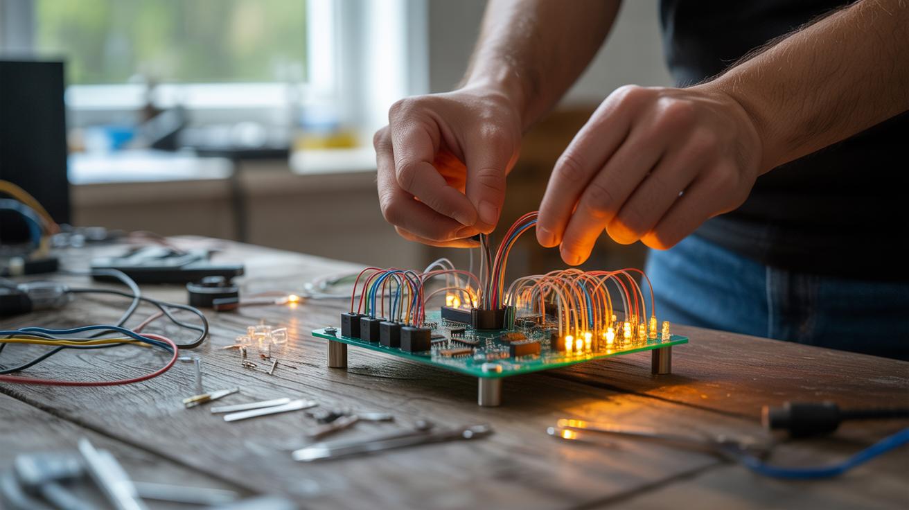
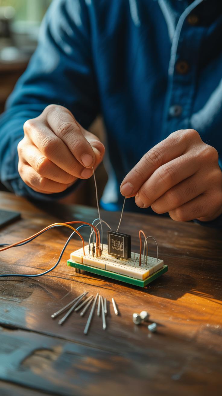
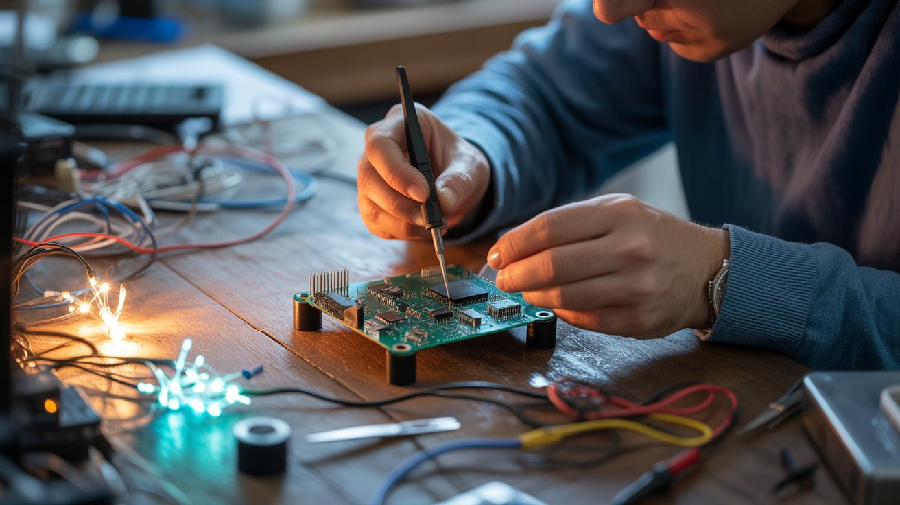
Electronics mini projects are small, doable projects that you can build easily at home or school. They help you learn how electronic circuits work by putting theory into practice. These projects use simple components and tools, making them perfect for beginners and hobbyists. Exploring mini projects can sharpen your skills and spark your creativity.
This article explores electronics mini projects you can start today for fun. You will find clear ideas, what parts you need, and step-by-step guidance to dive into creating useful or entertaining devices. These projects teach you practical electronics in a hands-on way without needing advanced knowledge.
Understanding Basic Electronics
What is Electricity
Electricity might seem complicated at first, but it’s basically the flow of tiny particles called electrons moving through a material, usually a wire. Imagine water flowing through pipes—that’s kind of similar, except here, electrons carry energy that powers devices. This flow is called current, and it moves from a higher voltage point to a lower one.

In a simple circuit, electricity needs a closed path to travel. If there’s a break anywhere, the current stops. This is why a switch can turn something on or off—by opening or closing the circuit. Voltage can be thought of as the push that gets electrons moving, while current is the actual flow of those electrons. Without voltage, current won’t move, and nothing works.
Common Electronic Components
When you start mini projects, you’ll meet a few basic parts repeatedly. Getting to know these will help you understand and build your own circuits.
- Resistors: These limit the flow of electricity. Think of them as barriers that slow down the current. They control how much current reaches other parts like LEDs, preventing damage.
- Capacitors: These store and release energy. Sometimes they smooth out voltage changes or help create time delays. They’re not complicated but can be a bit mysterious until you experiment.
- LEDs (Light Emitting Diodes): These tiny lights turn electrical energy into light. They only allow current to flow one way, so you have to connect them correctly.
- Transistors: These act like electronic switches or amplifiers. You can turn a small signal into a bigger one or control bigger currents with them. Learning to use transistors can open a world of project possibilities.
When you work with these, you’ll start to see how simple parts combine to create interesting functions. Sometimes the best way to understand is just to grab some components and try stuff out—you might discover patterns you didn’t expect, and that’s part of the fun.
Tools and Materials Needed
Essential Tools
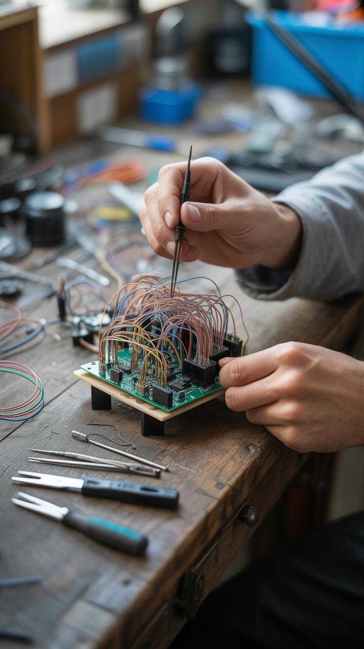
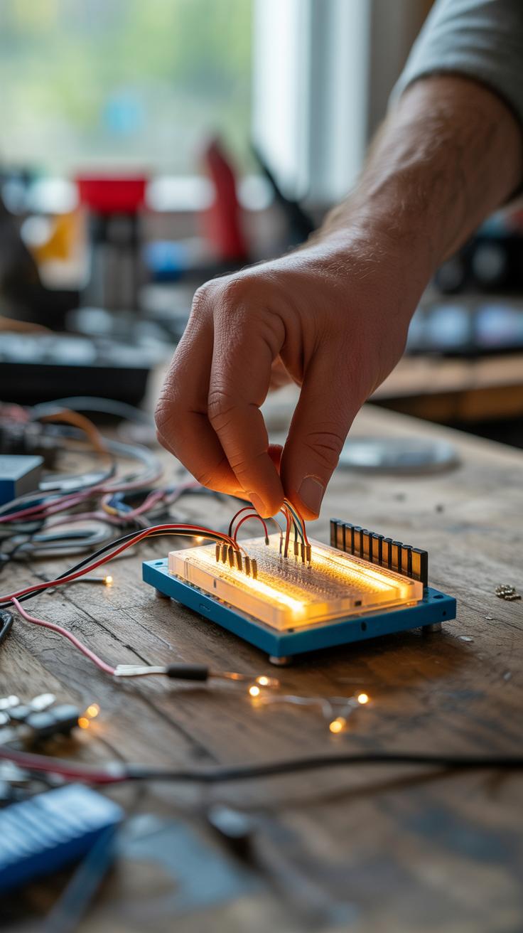
When starting with electronics mini projects, having the right tools makes a big difference. A soldering iron is probably the most talked-about tool. You’ll need one to join components permanently, but sometimes you might want to skip it, using a breadboard instead. That’s handy for quick testing or experimenting without making a mess.
A multimeter is another must-have. It helps measure voltage, current, and resistance—basically answering the “is this working?” question. I’ve found it saves a lot of guesswork. Some might overlook simple wire cutters, but they’re crucial when you want neat, manageable wires. Messy wiring can get frustrating fast.

Then there’s the breadboard itself. It’s sort of like a blank canvas, letting you slot parts in without soldering. If you’re into trying things out or learning, it’s a good place to start and saves time. You might not need every tool immediately, but these four—soldering iron, multimeter, wire cutters, and breadboard—really cover the basics for most projects.
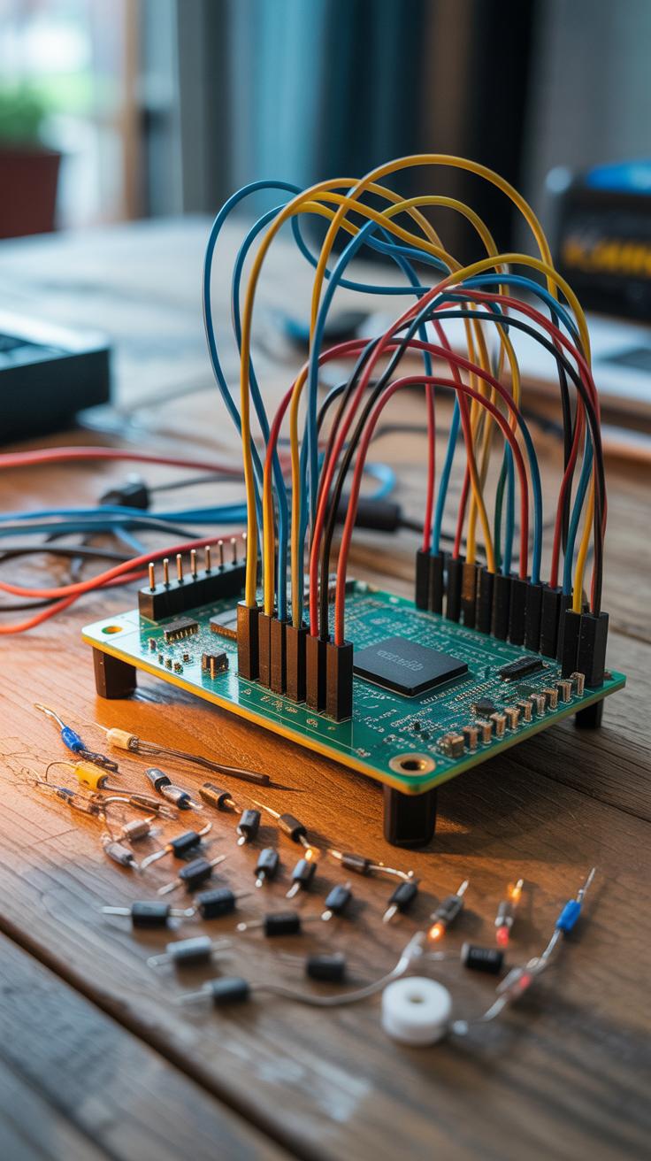
Basic Components to Have
Picking your first set of components feels a bit like assembling a survival kit—you want versatile and affordable parts. Resistors are always useful. They come in various values and help control current, which is critical almost everywhere. Capacitors follow, especially tiny ceramic ones, which you’ll use for smoothing signals or timing.
Don’t forget LEDs; they’re cheap and let you see circuits working immediately. There’s something satisfying about lighting one up yourself. Some transistors, like the 2N2222, are handy for switching and amplifying signals—perfect for small projects. Also, grab some basic switches and jumper wires to make connections easier.
Integrated circuits, like timers (think 555 IC), might seem complex at first but actually simplify certain projects. Starting with a small, well-chosen collection of these parts means you can test many ideas without chasing down unusual components each time. It might seem like collecting parts endlessly, but each one serves a clear purpose and will get plenty of use before you consider expanding your stash.
Simple LED Blink Project
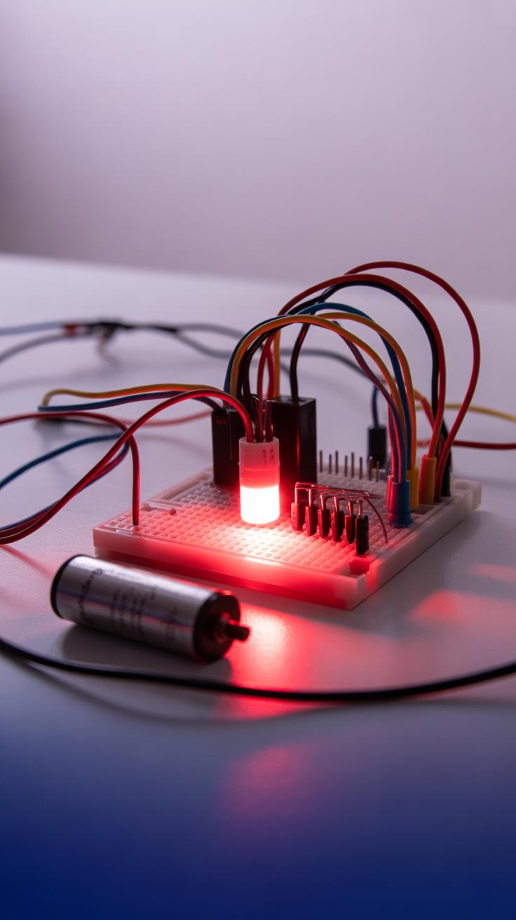
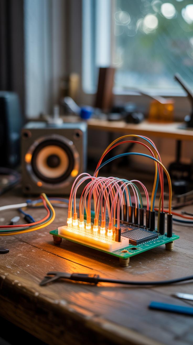
One of the easiest ways to get started with electronics is by making an LED blink. It’s a classic beginner project, but don’t let that fool you—it’s a neat way to understand both circuits and timing without getting overwhelmed. You’ll connect a few components on a breadboard and watch as your LED turns on and off rhythmically. It’s oddly satisfying, I think.
How it Works

The heart of this project usually involves a timer IC, like the popular 555 timer, or a basic microcontroller. If you use the 555 timer, it operates in what’s called “astable mode,” which means it creates a continuous pulse—a kind of steady on-off signal. These pulses turn the LED on and off at regular intervals. The timing depends on resistors and capacitors connected to the timer, which control how fast that blinking happens.
If you switch to a microcontroller, like an Arduino, you program it to send the on and off signal to the LED pin at whatever interval you choose. That makes it more flexible, but also a bit more complex at first.
Step-by-Step Assembly
Here’s how to put together the LED blink on a breadboard using the 555 timer (the simpler way):
- Insert the 555 timer IC into the breadboard, straddling the central gap so each pin is accessible.
- Connect pin 1 to ground and pin 8 to positive voltage (usually 5V).
- Attach resistors between pin 7 and pin 8, and between pin 7 and pin 6. These set the timing.
- Place a capacitor between pin 6 and ground; this component influences the blinking speed.
- Link pin 3 (output) to the long leg of the LED, then connect the LED’s shorter leg to ground through a current-limiting resistor.
- Double-check your connections and power the circuit. The LED should start blinking.
There’s a bit of trial and error involved, especially tweaking resistor and capacitor values to get the blink rate you want. It’s a hands-on way to learn how electronic components influence behavior.
Building a Light Sensor

Light sensors are surprisingly simple to make, and they’re pretty useful too. The core component you’ll need is an LDR, or Light Dependent Resistor. This little device changes its resistance based on how much light it senses—bright light lowers the resistance, while darkness increases it. It’s almost like the sensor “feels” the light creeping in.
For the project, you’ll also want a resistor (something around 10k ohm works well), a power source like a 5V battery or a USB supply, and a way to measure output, usually by connecting to an LED or a multimeter.
Here’s a simple way to put it together:
- Connect one leg of the LDR to the positive terminal of your power supply.
- Attach the other LDR leg to one end of your resistor.
- Hook the remaining resistor end to the ground.
- From the junction between the LDR and resistor, connect the wire to the input of an LED or a microcontroller analog pin to measure voltage.
As the light levels change, the voltage at the junction shifts, making the LED brighten or dim, or sending varying signals if you’re reading it digitally. Testing this is easy—simply shield the LDR with your hand or shine a flashlight on it and watch the reaction. Sometimes I find it fascinating how such a simple setup can detect daylight changes or trigger alarms.
Practically, you might use this sensor to automate lights that come on when it gets dark or build toys that respond to sunlight. Though basic, it opens many doors for experimentation. Ever thought how your room light could self-adjust with this? It’s worth a try.
Creating a SoundActivated LED

Understanding the Circuit
At its core, this project uses a microphone to pick up sound waves—like claps or speech—and then turns those signals into an electrical response that controls an LED. The microphone acts like a tiny ear, converting sound vibrations into small electrical signals.
Inside the circuit, these signals are often very weak, so an amplifier is used to boost them up to a level that can actually switch the LED on or off. Think of the amplifier as a volume knob that makes the sound signal louder for the electronics to “hear.” When a sound passes a certain threshold, the circuit triggers the LED to light up, sometimes even making it blink depending on how you design it.
Building Instructions
Start by gathering these parts:
- A simple condenser microphone or an electret mic module
- An operational amplifier or a transistor (to amplify the mic signal)
- A few resistors and capacitors for filtering and controlling signal strength
- An LED
- A power source (usually a 9V battery or similar)
Begin by connecting the mic input to the base of a transistor through a resistor. This will allow the transistor to act as a switch when sound is detected. Link the transistor’s collector to the positive supply via the LED and a current-limiting resistor. When sound hits the mic, the transistor switches on, lighting the LED.
This setup is fairly forgiving—if you don’t get the resistor values perfect, the LED might flicker or stay dim, which can still be fun to experiment with. I found that adjusting the resistor connected to the mic greatly affects sensitivity, sometimes a bit too sensitive.
Try testing the circuit by clapping near the mic or speaking loudly. If the LED doesn’t react, tweaking the resistor or adding a simple capacitor to filter out noise can help. It’s a good way to get a feel for how sound interacts with electronics, without much fuss over complicated parts.
Making a Mini Alarm Circuit
Alarm Circuit Basics
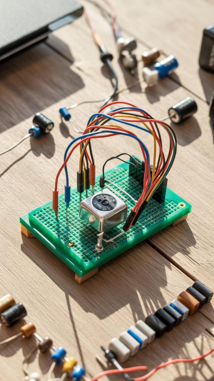
At its core, a simple alarm circuit is about detecting an unwanted event and making noise to alert you. Usually, it involves a sensor to spot the trigger—like a switch, a light sensor, or even a simple push-button—and a buzzer that sounds off when the sensor is activated. The sensor acts like a gatekeeper; when it changes state, the circuit powers the buzzer, drawing attention immediately.
The simplest setup often uses a basic switch sensor connected in series with a power source and a buzzer. When the switch is open, nothing happens. Close it—maybe someone opens a door or presses a button—and the buzzer starts sounding. You can add a resistor or transistor to control current flow if you want to be a bit more precise. This is a very raw but effective way to get an alarm working.
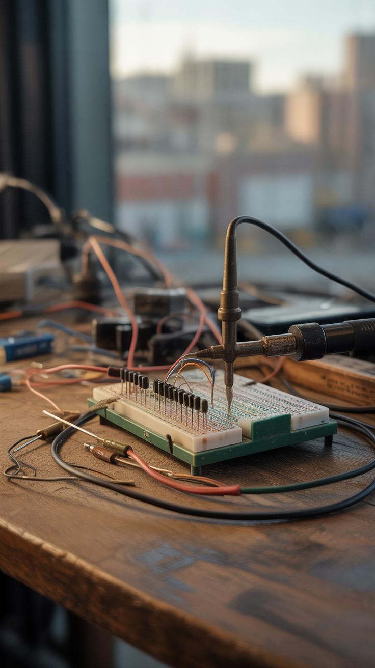
Assembly and Testing
Start with a breadboard—it makes life easier, especially if you want to tweak things. You’ll need a battery (say 9V), a buzzer, a simple switch or a cheap sensor, and some connecting wires. Connect the positive of the battery to one terminal of the sensor, then from the sensor to the buzzer’s positive terminal. Finally, complete the circuit by linking the buzzer’s negative back to the battery’s negative.

Test it by closing the sensor—either pressing the switch or triggering it somehow. If the buzzer beeps, you’re in business. If not, check your connections and battery power. It might take a few tries to get everything clicking, which is part of the fun. Don’t be shy about swapping parts or adding a resistor if the buzzer is too loud or too quiet. This hands-on testing helps you really understand how each piece works.
Working with Sensors

Sensors bring your mini projects to life by letting your circuits perceive the world around them. If you’re new to this, it might seem a bit tricky at first—connecting a tiny sensor and expecting it to “feel” temperature or motion doesn’t come naturally. But once you try, it’s surprisingly straightforward.
Types of Sensors
There are a few sensors that beginners tend to reach for. Temperature sensors, like the classic LM35 or DS18B20, measure heat and are quite easy to work with. Motion sensors, such as PIR sensors, detect nearby movement and can trigger alarms or lights. Then, light sensors—like photoresistors or photodiodes—measure brightness and can help your project react to changes in lighting.
Each sensor has its quirks. For example, PIR motion sensors need some time to “warm up” before they accurately detect movement. And temperature sensors might need a bit of calibration, depending on what you’re measuring. But that’s part of the learning.
Using Sensors in Projects
Wiring sensors usually means connecting three pins: power (often 5V or 3.3V), ground, and output. The output can be analog or digital signals. Analog outputs vary continuously depending on what’s being sensed, while digital outputs switch between on and off states.
You typically plug the sensor’s output into an analog or digital input pin on your circuit, like on a microcontroller or a breadboard setup. Then, you read the voltage changes and interpret them as meaningful data—temperature degrees, motion detected, or light intensity.
Sometimes, reading sensor signals feels like deciphering a language. You might need to map raw voltage values to real units, like degrees Celsius or lumens. That involves a bit of math or using libraries if you’re working with microcontrollers. But starting simple with direct readings and seeing how values change around stimuli is often more enlightening than just theoretical explanations.
Trying sensors one by one also gives you clues about their response time and sensitivity. Don’t rush it. Sometimes, waiting and observing is where you pick up insights no datasheet can offer.
Using a Microcontroller
What is a Microcontroller
A microcontroller is like the brain of many small electronics projects. It’s a tiny computer built into a single chip that can read inputs, process data, and control outputs. Think about a tiny command center directing signals from sensors or switches and making things happen, like turning on an LED or running a motor.
Unlike a regular computer, microcontrollers focus on specific tasks rather than general computing. That means they’re perfect for projects that need to sense and respond quickly and repeatedly. You’ll often find them in everyday gadgets—remotes, thermostats, or even toys.
If you imagine your project as a little machine, the microcontroller decides what that machine does based on the program you load. Making this decision is its core job. But sometimes, understanding its limits—like memory size or input pins—can be confusing at first. Keep that in mind as you start.
First Programming Steps
Getting started with programming a microcontroller feels tricky but it’s actually simpler than it seems. Most beginners use languages like C or even a block-based system to write instructions. At its core, you’re telling the microcontroller what to do, step-by-step.
Here’s a basic outline of what you’ll deal with:
- Setup code: Runs once when the microcontroller powers on. It sets the stage—it configures pins as inputs or outputs.
- Loop code: Runs over and over, checking inputs and controlling outputs.
For example, your code might check if a button is pressed. If yes, it turns on an LED. The logic sounds simple, but watching your project react in real time is surprisingly satisfying.
It’s also worth experimenting with small changes, then uploading your code and seeing what happens. Don’t expect perfection on your first try—sometimes a ‘bug’ is just a way for you to learn what the microcontroller understands and what it doesn’t.
Have you thought about which input or output you’d want to try first? A blinking LED is a classic start, but even that can teach a lot about timing and control flow. I found that just playing with delays and turning an LED on and off gave me a clearer picture of how code translates into action.
Troubleshooting Common Issues
When your mini project doesn’t work as expected, it’s tempting to get frustrated or just give up. But troubleshooting is part of the process—and it’s often where the real learning happens. The first step is to stay calm and slowly check each part of your circuit and code.
Testing and Debugging
Start by using a multimeter to test your circuit. Measure voltage at different points to see if power is reaching where it should. Check continuity to make sure wires and connections aren’t broken. If a resistor or LED isn’t behaving right, measure its values directly—you might spot a faulty or misplaced part early on. Don’t guess; measure carefully.
Next, test your microcontroller pins if you’re using one. Are input and output pins working as intended? Sometimes a pin won’t respond because it’s not programmed correctly or damaged.
Making Corrections
If you find a loose wire or a wrong connection, fix it immediately. Recheck your wiring against the project diagram—it’s easy to mix up pins or skip a ground connection. For components, try swapping suspected faulty parts with new ones if you have spares. That little LED might just be burned out.
When it comes to code, insert print statements or debug outputs to see where things go off track. Sometimes one missing semicolon or a wrong variable name is all it takes to break the whole program. Step through your code slowly, and don’t hesitate to rewrite confusing sections.
Figuring out what went wrong can feel slow, but persistent testing and small corrections get you closer every time. What happens if your multimeter shows no voltage but your power supply is on? That’s a clue worth exploring further.
Conclusions
Working on electronics mini projects builds your understanding of circuits, components, and design. Such projects give you real experience connecting parts and troubleshooting. As you try more projects, your skills will grow, and you can move on to more complex builds.
Starting mini projects is easy and rewarding. By using everyday and special electronic components, you bring your ideas to life. This hands-on learning makes electronics clearer and more interesting. Now is a great time to pick a project and begin creating.