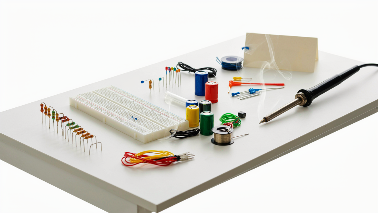
The Myth Of The Beginner Component

Simplification Kills The Thing You Actually Want
You want permission to start small so you don’t feel stupid. Here’s the mechanism: the electronics industry marketed “beginner” components to create product categories, not because they teach differently. A resistor functions identically whether you’re in week one or year ten. The real constraint isn’t the component’s complexity. It’s your mental model of what complexity means. Treating resistors as training wheels delays the actual skill: understanding how voltage, current, and resistance interact in a real circuit.
The conventional path wastes time by isolating components. You learn resistors alone, then capacitors alone, then transistors alone. This creates false separation. In real circuits, these components work together under specific conditions. You don’t learn electronics by memorizing component names. You learn by building systems where components fail or succeed based on their relationships. Start with a complete circuit. Use a resistor because the circuit demands it, not because it’s “easier.” The friction teaches faster than isolation ever could.
The Architecture Of Real Learning
Borrowed from systems theory: a resistor is a constraint. In complex systems, constraints define behavior more than components do. Remove a resistor from an LED circuit and nothing works. Change its value by half and the LED burns out. The component doesn’t matter. The relationship it creates matters. This is why beginners plateau fast on isolated component tutorials.
Build a circuit that requires you to calculate resistor values based on voltage and current needs. You’ll learn more in one iteration than ten isolated lessons. Grab a 9V battery, an LED, and resistors in different values. Connect them. Watch what happens at each value. The LED dims, brightens, dies. Now you understand resistors because you’ve seen the mechanism fail. Write down the values that work and why. That’s the protocol. Not memorization. Not theory without stakes.
Current Flow: More Than Just “Electrons Moving”

Why Drift Velocity Crushes Signal Speed In Your Head
You want to understand current so you can feel competent, but you’ve been fed a lie that makes no sense. Here it is: electrons move at centimeters per second through wire, yet your signal travels at nearly light speed. Both are true. Neither contradicts the other because they measure different things.

Drift velocity is how fast electrons physically shuffle through a conductor under voltage. In copper at room temperature, this speed sits around 0.1 to 1 millimeter per second. Signal propagation speed—the velocity of the electromagnetic wave traveling along the conductor—moves at roughly 50 to 90 percent of light speed depending on the medium. The confusion dissolves when you stop thinking of current as individual electrons sprinting and start thinking of it as a pressure wave through a crowd.
The mechanism works like this: when you apply voltage, the electric field propagates almost instantaneously through the conductor via electromagnetic radiation. That field pushes on all electrons simultaneously, creating the sensation of current. The electrons themselves barely move. What actually travels is the disturbance, the field itself. Your circuit responds to the field arrival, not to individual electron position.
This distinction matters in practice because it explains why your 1-meter wire doesn’t introduce noticeable delay in a DC circuit but does in high-frequency signals. At DC and low frequencies, drift velocity dominates your thinking. At RF and digital speeds, signal propagation speed becomes the constraint. A circuit designer ignores this relationship and builds a circuit that fails under conditions it should handle.
Electrons Break Physics You Thought Was True
Quantum mechanics isn’t abstract philosophy—it’s the actual mechanism electrons use to behave inside wire. In classical physics, an electron is a tiny charged ball bouncing through a lattice like a pinball. That model fails completely at the atomic scale. Electrons don’t have defined positions until measured. They exist as probability waves.
Inside a conductor, electrons occupy quantum states within energy bands. When you apply voltage, you’re not pushing balls forward—you’re tilting the energy landscape so electrons preferentially occupy states that drift toward the positive terminal. They tunnel through barriers, their momentum is never certain, and they exist in superposition until interaction pins them down. This is not metaphor. This is how current actually works at the physics level.

The practical result: electron behavior depends on material properties you can’t calculate from first principles without quantum math. Copper conducts differently than aluminum not because the atoms are sized differently, but because their electron band structures differ. Temperature affects conductivity because thermal energy excites electrons to different states, changing their mobility. Doping silicon with phosphorus works because phosphorus atoms contribute electrons to different quantum states than silicon alone provides.
When you design with semiconductors, you’re exploiting quantum tunneling and band gaps. When you measure current and get predictable results, you’re observing the statistical average of trillions of quantum events. The engineer who understands this builds circuits that work across temperature ranges and fabrication variations—the one who doesn’t blames “mysterious” failures on component tolerance.
The Feedback Loop Protocol: Mastering Control
How Systems Actually Self Correct
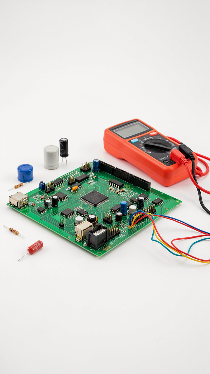
You want this section because you’re tired of circuits behaving unpredictably. You need control. Cybernetics borrowed the term “feedback” from mechanical governors on steam engines, and circuits work exactly the same way: input signal arrives, the circuit processes it, produces output, then compares that output back to the original input to adjust behavior. This loop is how every stable circuit stays stable. Without it, your amplifier screams into oscillation, your voltage regulator drifts, your motor spins out of control.
The mechanism is simple but non-negotiable. A sensor or tap-off point measures the output. That measurement gets subtracted from the desired target input, creating an error signal. The circuit amplifies this error and feeds it back into the system to reduce the gap. Negative feedback means the correction works against the deviation, killing instability. Positive feedback amplifies deviation and typically destroys the circuit. Most useful circuits run on negative feedback because it’s the only way to make electronics behave predictably across temperature changes, component tolerances, and aging.
Stability Before Everything Else
Common advice tells you feedback loops are “smooth and responsive.” That’s lazy thinking. What actually matters is whether your circuit stays within bounds or explodes into wild oscillation. Every feedback system has a stability window defined by how fast the loop corrects itself and how much delay exists before that correction takes effect. Too much delay relative to correction speed, and the system overshoots, then over-corrects, then oscillates indefinitely. Too little feedback and the system never reaches the target.

Phase shift is the silent killer most hobbyists ignore until their circuit fails. As signal frequency increases, components like capacitors and inductors shift when the signal arrives relative to when feedback hits the input. If enough phase shift accumulates, negative feedback can flip into positive feedback without warning, turning your careful design into a screaming oscillator. The practical fix: limit high-frequency content entering the feedback path using capacitors or resistors. Measure the loop gain and phase response before powering the full circuit. Oscillation prevention isn’t a feature. It’s the baseline requirement.
Resistors: The Unsung Heroes Of Current Control
The Relationship Between Voltage And Flow
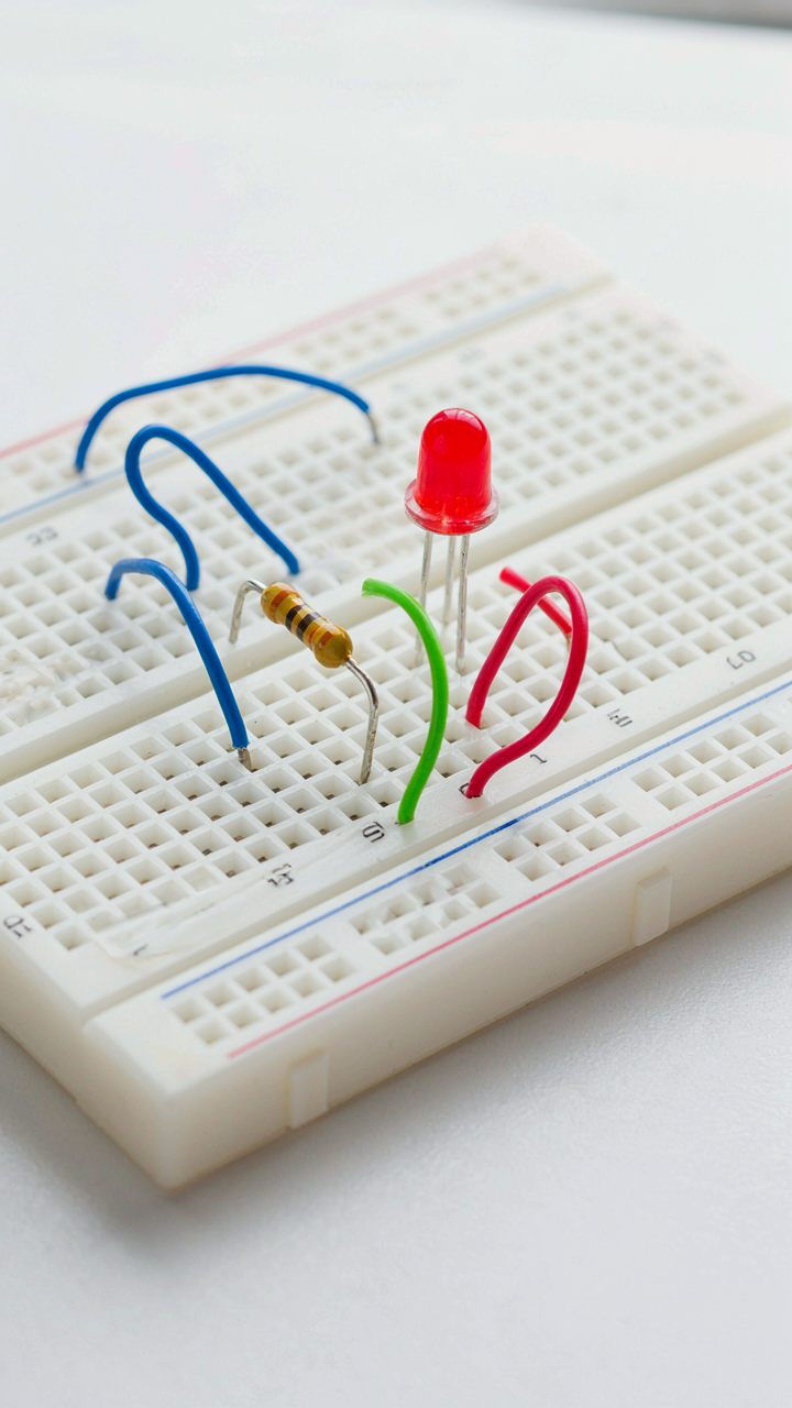
You want to understand resistors because you’re tired of breaking components and looking incompetent in front of people who actually know what they’re doing. Here’s the mechanism: Ohm’s Law is physics in action, not a formula to memorize. Voltage (electrical pressure), current (electron flow), and resistance (opposition to flow) don’t exist separately. Change one, and the others respond immediately. A resistor isn’t a passive obstacle. It’s a deliberate tool that scales this relationship predictably.
The math is simple: voltage divided by resistance equals current. In practice, this means a resistor lets you control how much current flows through any part of your circuit. If your LED needs 20 milliamps but your power source pushes 100 milliamps, a resistor drops the excess voltage and cuts the current to safe levels. Without understanding this relationship, you’re just guessing at component values and burning things out.
Material And Function: What Actually Changes
Most beginner advice treats resistor types as interchangeable, which is wrong. Different resistor materials and construction methods behave differently under stress, temperature, and frequency. Carbon film resistors are cheap and work fine for DC circuits at room temperature. Metal film resistors offer tighter tolerances and better stability over temperature swings. Wirewound resistors handle high power but introduce inductance, which matters if you’re working with AC signals or fast switching circuits.

The critical role resistors play depends entirely on where you place them. A current-limiting resistor protects an LED by reducing current before it reaches the component. A pull-up or pull-down resistor sets a default voltage state for a digital input when no signal is present. A voltage divider uses two resistors to create intermediate voltage levels from a single supply. Each application requires you to pick the right type and value. Pick wrong and your circuit behaves like you designed it without thinking.
Capacitors: Storing Energy, Not Just Charge
The Dielectric Material Is The Real Energy Reservoir
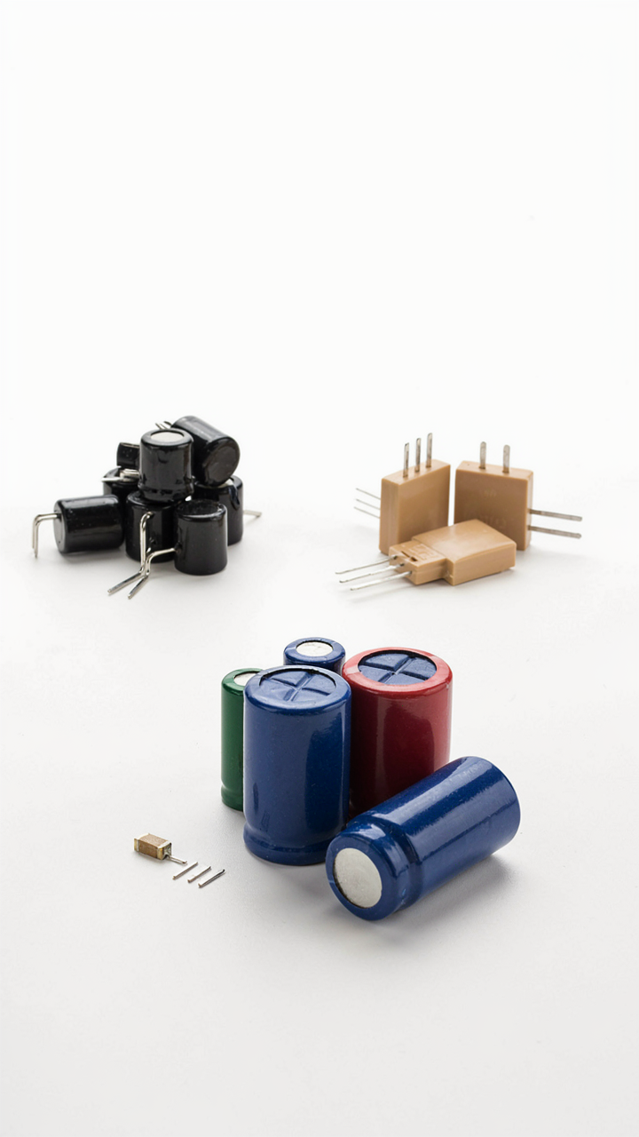
You want to understand capacitors because you’re tired of half-answers, and the real mechanism sits in a material most tutorials gloss over. Think of a capacitor like a battery, but instead of chemical reactions storing energy, the dielectric material physically holds an electric field between two plates. The dielectric is the actual storage mechanism, not the plates themselves.
The dielectric material resists electron flow and polarizes when voltage crosses it. This polarization creates an internal electric field that opposes the applied voltage, effectively storing energy in the material’s molecular structure. Different materials hold different amounts of energy at the same voltage: ceramic capacitors, film capacitors, and electrolytic capacitors all use different dielectrics because each material has a distinct permittivity rating. The permittivity determines how much charge the capacitor can hold per unit voltage. When you pick a capacitor for a circuit, you’re really choosing a dielectric material’s characteristics, not just a voltage rating.
Discharge Rates Depend On What’s Actually Connected
Most people think discharge is instantaneous, which is wrong and costs them real projects. Discharge rate depends entirely on the resistance in the circuit pulling current from the capacitor. With zero resistance, you’d get a theoretical instant dump. With actual resistance, discharge follows an exponential curve governed by the RC time constant: the product of resistance and capacitance in farads.

The equation matters because it predicts real timing in your circuits. A capacitor through a 1-kilohm resistor discharges much faster than the same capacitor through a 1-megohm resistor. Understanding this lets you design circuits that trigger at specific moments, smooth power delivery, or filter unwanted frequencies. In practical terms, measure the resistance your capacitor actually faces when it discharges, multiply it by the capacitance value, and that time constant tells you how long the capacitor takes to drop to 37 percent of its original voltage. Use this number to set flash durations, delay circuits, or audio filter cutoff points instead of guessing.
Diodes: The Unidirectional Gatekeepers Of Flow

How Bias States Control Electron Movement
You want to understand diodes because they’re the first component that makes you feel like you actually understand circuits instead of just copying schematics. Here’s the mechanism: a diode is a one-way valve for current, and like a valve, it has states. Think of economics—supply flows one direction until price (voltage) hits a threshold, then nothing moves. A diode works the same way with electrons.
A diode has two terminals: anode and cathode. When you connect positive voltage to the anode and negative to the cathode, you apply forward bias. Electrons move from cathode to anode through the semiconductor material, current flows, and the diode conducts. The voltage needed to start this flow is the forward voltage drop, typically 0.7 volts for silicon diodes and 0.3 volts for germanium. Reverse this polarity and you apply reverse bias. Now the diode blocks current almost completely because you’re pushing electrons away from where they need to go. At a certain reverse voltage threshold called breakdown voltage, the diode stops blocking and conducts in reverse. Most designs avoid this state, but it’s the mechanism that lets some components (like Zener diodes) regulate voltage.
Turning AC Into DC And Protecting Circuits
The textbooks call this rectification but skip the actual reason you care: diodes let you convert AC power into DC power, which is what every battery-powered device needs. Place a single diode in an AC circuit and current only flows during the positive half-cycle. The negative half blocks. Stack four diodes in a bridge configuration and you redirect both half-cycles to flow the same direction, giving you pulsing DC instead of useless alternating current.

Signal isolation is the second mechanism that matters. When two circuits shouldn’t directly touch but need to pass information, you use diodes to decouple them. A diode lets a signal through in one direction while blocking reverse interference. In audio circuits, mixers, and switching applications, this prevents one stage from loading down another or feeding noise backward. The key step is selecting the right diode type for your frequency and current—fast switching diodes for high-frequency circuits, rectifier diodes for power supplies. Test the diode with a multimeter in continuity mode to confirm it conducts forward and blocks reverse before trusting it in your circuit.
Transistors: Amplifying And Switching Reality
How BJTs And FETs Actually Differ
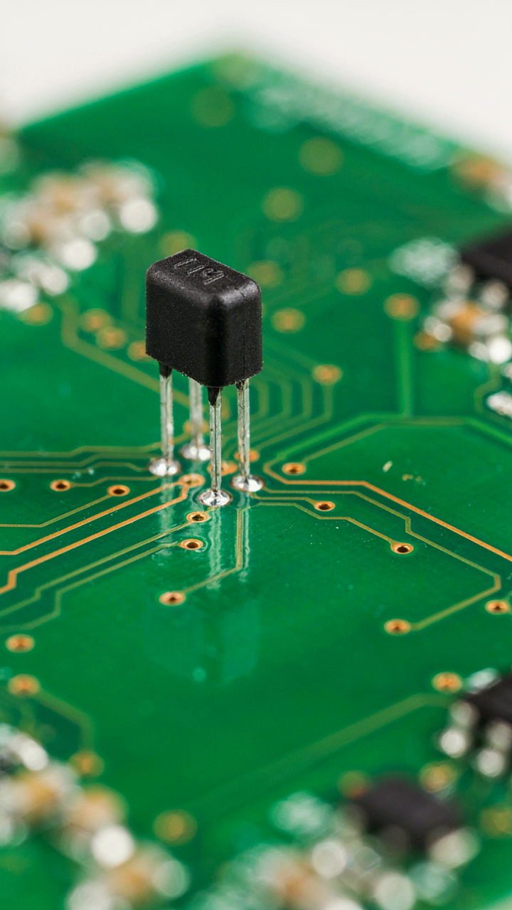
You want to understand transistors because you think it’ll make you look competent at the hardware level, but the real mechanism is simpler than you assume. A bipolar junction transistor operates on current control: you push current into the base, and a larger current flows from collector to emitter. A field-effect transistor operates on voltage control: you apply voltage to the gate, and it modulates the resistance of the channel between source and drain. The physics is different, the control signal is different, and the output behavior follows that difference.
Current amplification in BJTs means small base current produces large collector current. Voltage amplification in FETs means gate voltage creates an electric field that pinches or opens a conducting channel. BJTs saturate when heavily forward-biased, meaning they stop acting like amplifiers and become resistive switches. FETs enter cutoff and triode regions based on gate voltage relative to source and drain. Most hobbyist circuits use BJTs for simplicity or FETs for low power consumption. The choice depends on your circuit requirement, not on fashion or what you read on forums.
The Switch That Enables Every Digital System
Treating transistors only as amplifiers misses why they matter. A transistor as a switch is the foundational unit of digital logic. Apply the right voltage or current to the control pin, and the transistor blocks current flow or conducts it fully. This on-off behavior, repeated and combined, builds logic gates, processors, and memory. Every “1” or “0” in your computer comes from transistors switching between these two states at precise timing intervals.

When a transistor switches, it transitions between cutoff (no conduction) and saturation (maximum conduction). This binary nature makes it the building block for AND gates, OR gates, NOT gates, and every digital circuit that follows. The speed of this switching determines processor clock speed. The size and density of transistors packed onto silicon determine compute power per unit area. Understanding transistors as switches, not amplifiers, is the mental model that unlocks why Moore’s Law worked and why scaling down transistor size matters.
Inductors: Counter Intuitive Magnetic Energy
How Magnetic Fields Store Energy
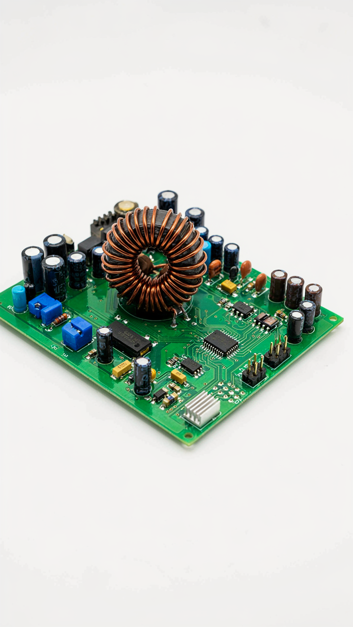
You want to understand inductors because they’re the component everyone glosses over, and that gap in knowledge costs you real debugging time. Physics borrows the concept of inertia from mechanics, and an inductor is electromagnetic inertia: it resists changes in current the same way mass resists changes in velocity. When current flows through a coil, the magnetic field around it stores energy. Cut the current, and that field collapses, forcing voltage to spike in the opposite direction.
Faraday’s law of electromagnetic induction states that a changing magnetic flux induces a voltage. An inductor quantifies this relationship: inductance measures how much voltage appears for a given rate of current change. The formula is V equals L times dI/dt. That spike you see when you kill power to an inductor circuit isn’t a glitch. It’s the stored magnetic energy demanding a path out. Ignore this and you’ll fry switching circuits and relays.
Resistance And Filtering In Real Circuits
The common advice treats RL circuits like resistor-inductor passive networks. That’s incomplete. An RL circuit is an energy management system where the inductor smooths current transitions and the resistor burns off that energy as heat. In a low-pass filter, the inductor blocks sudden current changes, forcing high-frequency signals to take longer paths through the circuit. This is why inductors appear in power supplies and audio stages.

Time constant matters more than the individual component values. Calculate it as L divided by R. This number tells you how fast the circuit responds to input changes. A fast time constant means the inductor’s influence fades quickly. A slow one means magnetic effects dominate longer. In switching regulators, you deliberately choose inductance to store energy during the on-phase and release it during the off-phase, creating DC output from pulse width modulation. The inductor bridges the gaps where the switch sits open.
IC Chips: The Architectures Of Modern Systems
What Happens Inside The Black Box
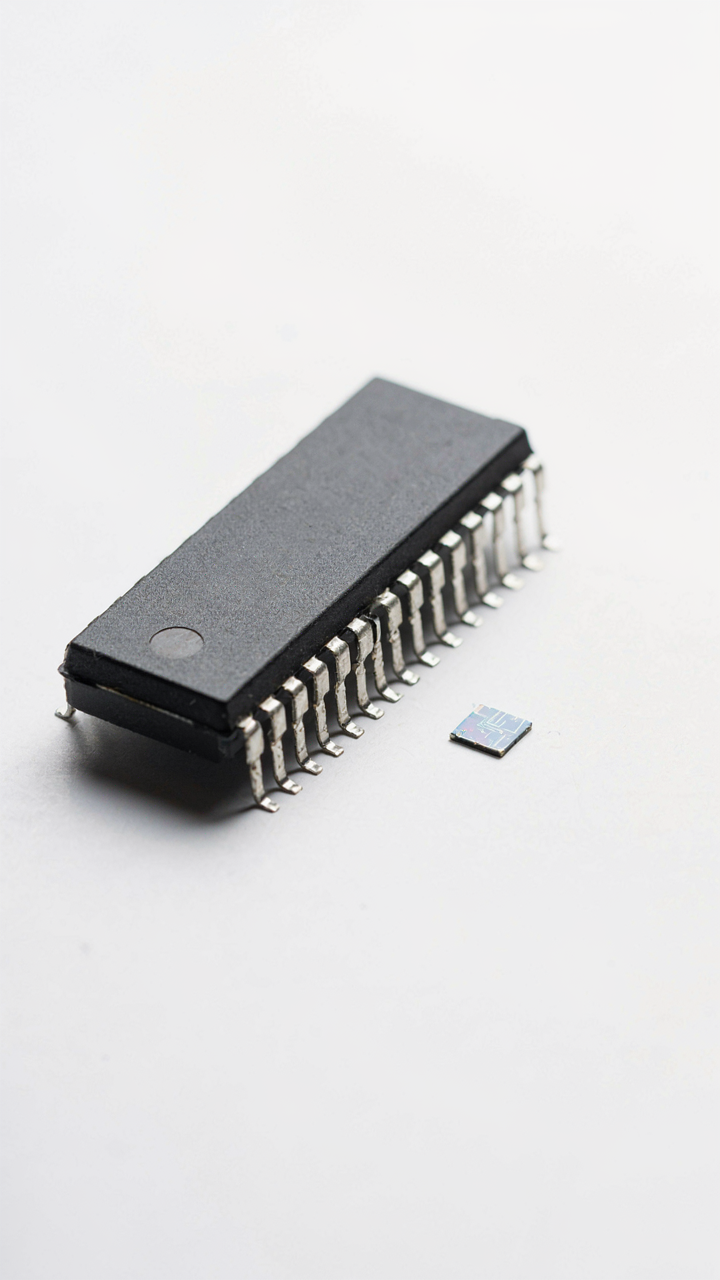
You want to understand IC chips because you’re tired of treating them like magic. Here’s what actually matters: an IC chip is a collection of transistors etched onto silicon, arranged in patterns that perform logic operations. Think of it like military strategy applied to electrons—each transistor acts as a soldier following conditional orders. When voltage hits the input, transistors switch on or off in sequence, creating a cascade of decisions that produce an output. That’s the entire mechanism.
The silicon die sits at the center, typically measuring millimeters across. Manufacturers use photolithography to etch microscopic patterns onto the surface, creating pathways where current flows. The smaller the transistors, the more you can fit on a single chip. Modern processes shrink features down to nanometers. Metal layers on top connect these transistors into functional circuits. The whole assembly gets packaged in plastic or ceramic with metal pins or balls sticking out, which you solder to a circuit board. Those pins are just the interface between the internal logic and your external circuit.
Microcontrollers Versus ASICs: Picking The Right Brain
The common advice here is incomplete: people say pick a microcontroller if you need flexibility and an ASIC if you need speed. Both statements are true but miss the real trade-off. A microcontroller is a general-purpose computer on a chip—it has a processor core, memory, and I/O pins, all programmable. You write code that runs on it, controlling its behavior. An ASIC is application-specific, meaning its logic is fixed at manufacturing time. You cannot reprogram it. That difference determines everything about cost, power consumption, and time to market.
Microcontrollers cost less upfront because manufacturers produce millions of identical units. You pay nothing for design work. ASICs require custom design and expensive fabrication masks, so you only use them when you need extreme volume or extreme performance that a microcontroller cannot deliver. An ASIC running the same task will use less power and run faster because its logic path is optimized for that single job. The catch: if your design changes, you scrap the ASIC and start over. With a microcontroller, you rewrite the code and ship the next batch tomorrow. Pick a microcontroller for prototypes, small production runs, and anything that might evolve. Pick an ASIC only when volume justifies the engineering cost and your requirements are locked down.
Soldering Beyond The Solder Joint: The Heat Transfer Method
Why Heat Matters More Than Your Iron’s Wattage
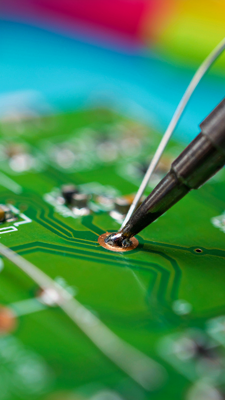
You want to believe that a bigger soldering iron means better joints. It doesn’t. What actually determines whether your component survives the process is how heat moves into the joint itself, not how hot your tool gets. Heat transfer is the physics problem you’re solving every time you touch iron to pad. The solder melts not because the iron is hot, but because thermal energy conducts through the pad, the trace, and the component lead simultaneously. Get the mechanism wrong and you cook the component or leave a cold joint that fails weeks later.
The real work happens in the first three to five seconds. Your iron must transfer enough heat to the thermal mass around the joint to raise everything above solder’s melting point at the same time. This is why component leads conduct heat away from your joint, why large copper planes act as heat sinks, and why tiny surface-mount devices need different techniques than through-hole work. The iron’s job is not to melt solder directly onto a pad. The iron’s job is to heat the pad and lead until they melt the solder themselves.
Wet And Shiny Beats Every Myth In The Textbook
The common advice about joint inspection is incomplete. Visual inspection catches obvious failures, but structural integrity is a separate question. A joint can look wet and shiny under magnification yet still be mechanically weak if the solder didn’t fully wet the lead or the pad had oxide contamination at contact time.
- Wetting angle: Solder should flow and spread across both the pad and lead, creating a concave meniscus. Poor wetting means solder beads up and pulls away, leaving voids and weak mechanical attachment.
- Lead-to-pad contact: The lead must physically touch the pad before heat melts the solder. If flux burns off before contact or the lead sits proud of the pad, heat won’t transfer effectively.
- Oxide layer removal: Flux chemically removes oxides from copper surfaces during heating. If your iron cools the joint too fast or you move it away too soon, the oxide reforms and the solder never bonds.
- Thermal stress on components: Through-hole components experience mechanical stress as solder cools and contracts. Surface-mount devices crack if you cool them too quickly or bend the lead after soldering.
- Cold joint signature: A dull, grainy surface indicates incomplete melting. Solder crystals didn’t form properly, creating high electrical resistance and mechanical fragility that fails under vibration or thermal cycling.
Real inspection means applying mechanical stress to the joint after it cools. Flex the lead gently. If it moves freely or the joint cracks, you have a structural failure that a camera never would have revealed. The protocol is simple: solder, cool without disturbance, inspect visually, then stress-test by hand before your circuit sees power.
The Only Component Holding You Back Is Your Unwillingness To Break The Rules

Most hobbyists memorize resistor color codes and never touch a soldering iron. They consume content instead of creating circuits. The shift that matters isn’t understanding components better. It’s accepting that breaking something teaches you more than reading about it ever will. Grab a breadboard today, wire up an LED with a resistor, and intentionally fry it. Failure moves you forward faster than perfection ever could. You don’t need permission to experiment.